Structure of Electric Motors | The Complete Guide
17/02/2025

Sam Nie
Hello every one. This is Sam Nie, the CEO of LUPMOTORS. With 10 year's technical and manufacture experience in the field of 3-phase electric motor, I can provide you definitive guides in the knowledge of 3-phase industrial electric motors,which will help you a lot in selecting electric motors for your applications.
Electric motors power nearly every machine around us. From industrial automation to household appliances, these machines work behind the scenes, converting electrical energy into motion. But how exactly do they work? What makes up their structure? And why do some motors perform better than others?
This guide will take you deep into the structure of electric motors, explaining each component in detail, backed by real-world engineering insights. Whether you’re an engineer, technician, or just someone curious about motors, this guide will equip you with everything you need to know.
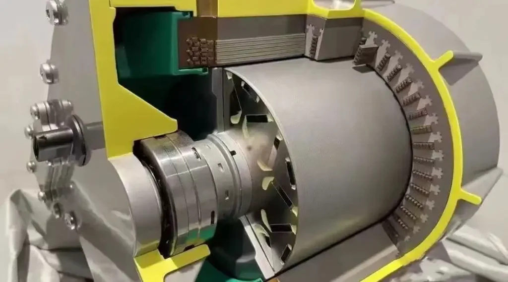
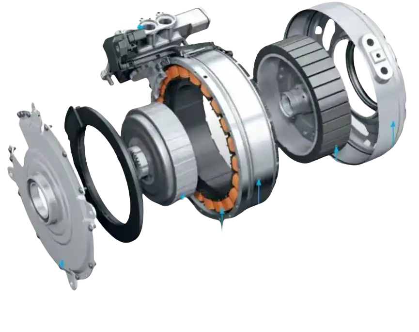
- A detailed illustration of every electric motor component
- Key materials and insulation types that affect performance
- How stators, rotors, and bearings work together
- The latest trends in motor design and efficiency
Let’s get started.
Table of Contents
1.Basic Structure of an Electric Motor
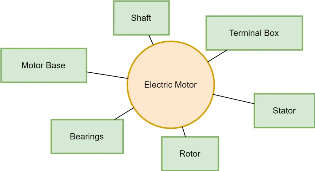
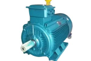
An electric motor consists of six essential components:
-

Stator
The stationary part that generates the magnetic field
-

Rotor
The rotating part that interacts with the stator
-

Bearings
Support the rotor and reduce friction
-

Shaft
Transfers mechanical energy from the motor to the load
-

Motor Base
Provides structural support
-

Terminal Box
Connects the motor to electrical power
Each of these components plays a vital role in motor performance. Now, let’s start with the most critical part—the stator.
1.1 Stator
2.1.1 Function and Importance
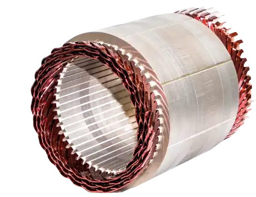
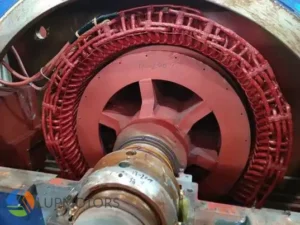
The stator is the heart of the motor. It generates the rotating magnetic field, which drives the rotor. Without a properly designed stator, the motor cannot effectively generate motion. The stator consists of the stator core and the stator winding.
2.1.2 Stator Core: Concept and Function
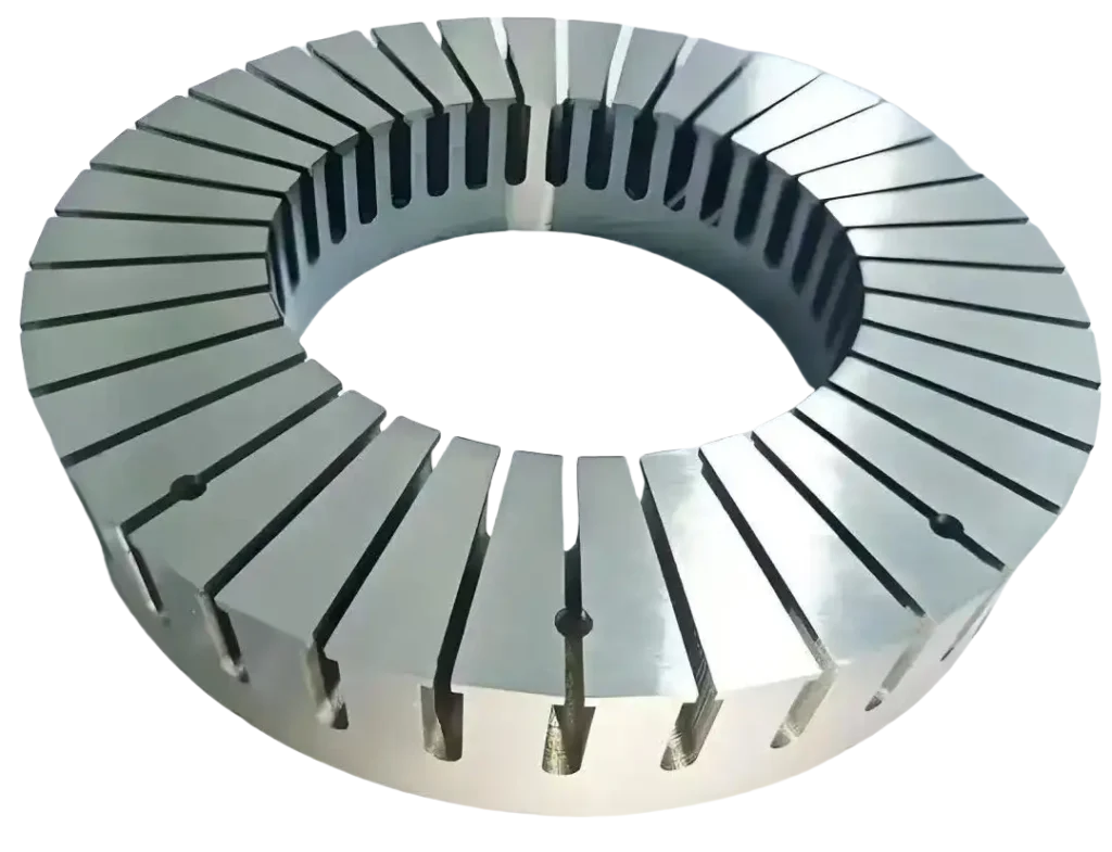
The stator core (iron core) is a laminated steel structure that houses the windings. It enhances magnetic flux flow, reducing energy loss due to eddy currents.
2.1.2.1 Stator Core Structure
A stator core consists of:
- Thin laminated steel sheets (0.35mm–0.65mm thick) to minimize electrical losses
- Slots to hold the stator windings
- Ventilation ducts to dissipate heat
2.1.2.2 Stator Core Slot Types
The stator core of an electric motor can be classified into two main types of windings based on the shape of the coils and how they are arranged within the slots:
1.Concentrated Winding
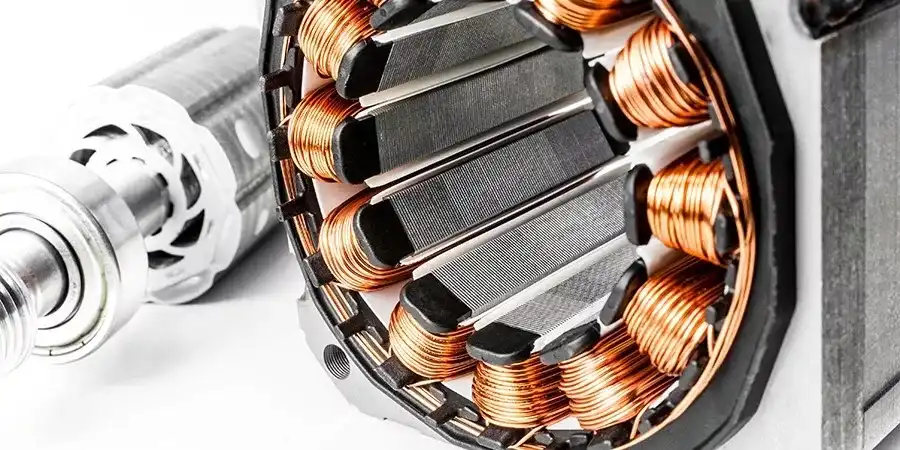
In a concentrated winding, each magnetic pole is formed by a single coil or a small number of coils wrapped together. The coils are rectangular in shape, wrapped tightly, and embedded into the stator slots after insulation treatment.
Structural Features
- Simple construction – Fewer coils make manufacturing easier.
- Stronger back electromotive force (EMF) – Produces higher torque at low speeds.
- High torque density – Ideal for applications where compact design is necessary.
Limitations
- Lower efficiency – Produces higher harmonic losses.
- Significant torque ripple – Leads to fluctuations in motor output.
- Higher losses at high speeds – Increases heat generation, especially in the windings and permanent magnets.
💡 Fact:
Concentrated windings are commonly used in hub motors for electric bicycles, small servo motors, and compact high-dynamic drives where efficiency is less critical but high torque at low speeds is required.
2. Distributed Winding
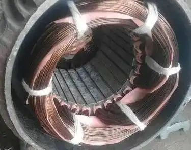
A distributed winding consists of multiple coils that are evenly spread across several stator slots. Unlike concentrated windings, the stator poles do not have protruding magnetic poles, and each phase winding is distributed across multiple slots.
Structural Features
- Lower harmonic content – Reduces torque ripple and improves efficiency.
- Better thermal dissipation – Helps in reducing heat buildup during operation.
- Higher overall motor efficiency – Preferred for industrial three-phase motors.
Types of Distributed Windings
- Improved smoothness of operation – Reduces torque ripple.
- Higher efficiency at high speeds – Reduces iron and winding losses.
- Better suited for industrial applications – Used in three-phase induction motors and large synchronous machines.
💡 Fact:
Most industrial motors use distributed windings due to their higher efficiency, better cooling, and lower harmonic losses, making them ideal for HVAC systems, industrial conveyors, and high-speed electric drives.
2.1.2.3 Material Choices and Their Impact on Performance
The stator core material significantly affects efficiency and heat dissipation. Different motors use different materials based on their voltage and power rating.
Motor Type | Stator Core Material | Lamination Thickness |
Low-voltage motors (≤1000V) | Cold-rolled silicon steel | 0.35mm – 0.5mm |
High-voltage motors (>1000V) | High-grade silicon steel | 0.5mm – 0.65mm |
Energy-efficient motors (IE3, IE4) | Ultra-thin grain-oriented steel | 0.20mm – 0.35mm |
💡 Fact:
Using thinner laminations (≤0.35mm) can reduce iron losses by up to 25%, improving efficiency
Learn More about Electric Motors?
LUPMOTORS will send you articles to your Email every week.
100% Free! No Credit Card!
1.1.3 Stator Windings: Concept and Function
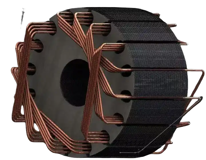
The stator windings are copper or aluminum coils wrapped around the stator core. Their role? To generate a rotating magnetic field that interacts with the rotor to create motion.
A well-designed winding system improves:
- Motor efficiency – Lower electrical losses
- Heat dissipation – Prevents overheating
- Durability – Extends motor lifespan
Without proper stator windings, a motor wouldn’t function at all.
1.1.3.1 Structure of Stator Windings
Stator windings are arranged in coils, forming multiple phases (typically three for industrial motors). These coils are embedded in the stator slots and insulated to prevent short circuits.
Common Winding Structures:
-

Lap Winding
Used in high-power motors for better current distribution
-

Wave Winding
Found in low-power motors, offering simpler manufacturing
💡 Fact:
Most industrial motors use three-phase windings because they provide smoother operation and higher efficiency than single-phase windings.
1.1.3.2 Stator Winding Insulation
Insulation prevents electrical failures and extends motor lifespan. There are three key insulation areas:
A. Ground Insulation
- Protects windings from ground faults
- Uses mica, epoxy resin, or polyester film
B. Phase Insulation
- Prevents short circuits between phases
- Uses polyimide tape or Nomex sheets
C. Turn-to-Turn Insulation
- Stops adjacent turns in a coil from shorting
- Uses thin polyester coatings
💡 Fact:
Industry Standard: High-voltage motors require Class F or Class H insulation, rated for 155°C–180°C
1.1.3.3 Stator Windings and Magnetic Field Generation
When AC current flows through the stator windings, it creates a rotating magnetic field (RMF). This field interacts with the rotor, causing it to spin and produce motion.
The strength of this magnetic field depends on:
-

Number of windings
More turns = stronger field
-

Current flow
Higher current = greater force
-

Coil arrangement
Symmetry improves efficiency
1.1.3.4 Stator Materials
The material used in windings affects efficiency, resistance, and heat generation.
| Material | Conductivity (IACS%) | Thermal Conductivity (W/m·K) | Used In |
|---|---|---|---|
| Copper | 100% | 400 W/m·K | Most industrial motors |
| Aluminum | 61% | 237 W/m·K | Budget-friendly motors |
💡 Fact:
Fact: Copper windings reduce electrical losses by 30% compared to aluminum, making them the top choice for high-efficiency motors
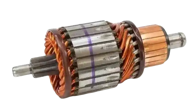
1.2. Rotor
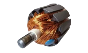
The rotor is the moving part of an electric motor. It spins inside the stator and converts electrical energy into mechanical motion. Without a well-designed rotor, a motor would be inefficient, noisy, or even fail entirely.
1.2.1 Role and Functionality
The rotor’s job is simple but crucial: it rotates when exposed to the stator’s magnetic field, transferring torque to the motor’s shaft. This movement is what drives fans, pumps, conveyors, and countless other machines.A rotor typically consists of:
-

Rotor core
A laminated steel structure
-

Rotor windings
Conductive bars or coils
-

Shaft
Transfers rotational energy
-

Cooling system
Dissipates heat
1.2.2 Rotor Core: Function, Material, and Structure
Function:
- Acts as a path for magnetic flux
- Provides mechanical stability for rotor windings
- Helps in cooling by allowing air circulation
Material Choices:
Motor Type | Core Material | Lamination Thickness |
Small motors (<10 kW) | Cold-rolled silicon steel | 0.35mm – 0.5mm |
Medium motors (10–200 kW) | High-silicon steel | 0.5mm – 0.65mm |
Large industrial motors (>200 kW) | Specialty laminated steel | 0.65mm – 1mm |
💡 Fact:
Using thinner laminations (0.35mm) in high-efficiency motors reduces iron losses by up to 40%
Structural Differences in Small vs. Large Motors:
- Small asynchronous motors use thinner laminations for better efficiency.
- Large industrial motors require thicker laminations to handle high torque.
1.2.4 Rotor Windings: Purpose and Structure
The rotor windings carry current and interact with the stator’s magnetic field to generate motion. There are two main types of rotor windings:
Squirrel Cage Rotor
What is Squirrel Cage Rotor?
A squirrel cage rotor consists of multiple conductive bars placed inside the rotor slots, connected at both ends by two annular end rings. When the rotor core is removed, the structure resembles a squirrel cage, giving it its name.
In small cage motors, the rotor typically uses a cast aluminum bracket structure, which is cost-effective and lightweight. However, for high-power motors (above 100 kW), the rotor is constructed using copper bars and copper end rings, which are welded together to enhance conductivity and efficiency.
Advantages:
- Simple design → Low maintenance
- High durability → No brushes to wear out
- Common in industrial AC motors
Used in:
Induction motors (low and medium power applications)
💡 Fact:
Over 90% of industrial motors use squirrel cage rotors due to their ruggedness and low maintenance
Wound Rotor
What is the Wound Rotor ?
The wound rotor features windings that closely resemble stator windings, forming a symmetrical three-phase winding system. Typically, it is connected in a star (Y) configuration, with the three output terminals linked to three collector rings mounted on the rotating shaft. These rings allow the rotor windings to connect to an external circuit via brushes, enabling precise control of resistance and torque during motor operation.
What is the Advantages of the Wound Rotor?
- Adjustable torque & speed → More control over motor performance
- Better for heavy loads → Used in cranes, mills, and elevators
What is the Feature of the wound rotor?
The wound rotor motor has a more complex structure than the squirrel cage motor, which limits its widespread application. However, its unique design allows for precise control of starting, braking, and speed regulation by inserting additional resistors or components in series with the rotor circuit via the collector rings and brushes. This adjustability makes wound rotor motors ideal for applications requiring smooth speed control within a specific range. They are commonly used in cranes, elevators, air compressors, and other heavy-duty machinery where gradual acceleration and controlled torque are essential.
💡 Fact:
Wound rotor motors can deliver 200%–300% of rated torque at startup, making them ideal for heavy-load machinery
1.2.5 Rotor Insulation: Protection Against Electrical Failures
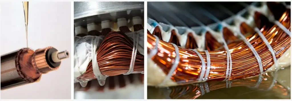
Rotor insulation is critical in preventing short circuits, overheating, and motor failure. Just like stator insulation, rotor insulation is divided into three main types:
1.Concentrated Winding
- Prevents leakage current from the rotor to the motor frame
- Typically made of mica, polyester film, or epoxy resin.
- Essential in high-voltage motors to avoid breakdown
2.Phase Insulation
- Prevents short circuits between different rotor windings.
- Uses polyimide tape or Nomex paper to separate phases.
- Helps maintain stable current flow in wound rotor motors.
3.Turn-to-Turn Insulation
- Prevents adjacent wire turns from shorting.
- Uses thin enamel coatings on copper wires.
- Crucial in high-speed motors, where voltage spikes can damage windings.
💡 Fact:
Fact: In high-voltage motors (>6.6kV), insulation breakdown is a leading cause of failure. Using Class H insulation (rated for 180°C) extends motor life.
Learn More about Electric Motors?
LUPMOTORS will send you articles to your Email every week.
100% Free! No Credit Card!
1.2.6 Differences Between Induction and Synchronous Rotors
Not all rotors function the same way. Induction rotors and synchronous rotors operate on different principles and are suited for different applications.
Feature | Induction Rotor | Synchronous Rotor |
How It Works | Current is induced by the stator’s magnetic field | Requires an external DC excitation |
Speed | Always slightly less than synchronous speed | Runs at exact synchronous speed |
Start-up | Starts on its own due to electromagnetic induction | Needs external excitation or a damper winding |
Efficiency | Slightly lower due to slip | Higher efficiency at full load |
Common Uses | Pumps, fans, conveyors | Generators, precision applications |
1.2.2 Rotor Core: Function, Material, and Structure
Function:
- Acts as a path for magnetic flux
- Provides mechanical stability for rotor windings
- Helps in cooling by allowing air circulation
Material Choices:
💡 Fact:
Using thinner laminations (0.35mm) in high-efficiency motors reduces iron losses by up to 40%
Structural Differences in Small vs. Large Motors:
- Small asynchronous motors use thinner laminations for better efficiency.
- Large industrial motors require thicker laminations to handle high torque.
1.2.4 Rotor Windings: Purpose and Structure
The rotor windings carry current and interact with the stator’s magnetic field to generate motion. There are two main types of rotor windings:
Squirrel Cage Rotor
What is Squirrel Cage Rotor?
A squirrel cage rotor consists of multiple conductive bars placed inside the rotor slots, connected at both ends by two annular end rings. When the rotor core is removed, the structure resembles a squirrel cage, giving it its name.
In small cage motors, the rotor typically uses a cast aluminum bracket structure, which is cost-effective and lightweight. However, for high-power motors (above 100 kW), the rotor is constructed using copper bars and copper end rings, which are welded together to enhance conductivity and efficiency.
Advantages:
- Simple design → Low maintenance
- High durability → No brushes to wear out
- Common in industrial AC motors
Used in:
Induction motors (low and medium power applications)
💡 Fact:
Over 90% of industrial motors use squirrel cage rotors due to their ruggedness and low maintenance
Wound Rotor
What is the Wound Rotor ?
The wound rotor features windings that closely resemble stator windings, forming a symmetrical three-phase winding system. Typically, it is connected in a star (Y) configuration, with the three output terminals linked to three collector rings mounted on the rotating shaft. These rings allow the rotor windings to connect to an external circuit via brushes, enabling precise control of resistance and torque during motor operation.
What is the Advantages of the Wound Rotor?
- Adjustable torque & speed → More control over motor performance
- Better for heavy loads → Used in cranes, mills, and elevators
What is the Feature of the wound rotor?
The wound rotor motor has a more complex structure than the squirrel cage motor, which limits its widespread application. However, its unique design allows for precise control of starting, braking, and speed regulation by inserting additional resistors or components in series with the rotor circuit via the collector rings and brushes. This adjustability makes wound rotor motors ideal for applications requiring smooth speed control within a specific range. They are commonly used in cranes, elevators, air compressors, and other heavy-duty machinery where gradual acceleration and controlled torque are essential.
💡 Fact:
Wound rotor motors can deliver 200%–300% of rated torque at startup, making them ideal for heavy-load machinery
1.2.7 How Rotor Design Affects Efficiency
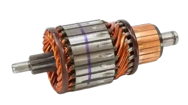
1. Rotor Bar Material:
Copper vs. Aluminum
- Copper bars reduce losses by 30% compared to aluminum.
- Aluminum bars are cheaper but generate more heat.
💡 Fact:
High-efficiency induction motors (IE3, IE4) use die-cast copper rotors to cut energy losses
2.Rotor Core Lamination Thickness
- Thinner laminations (0.35mm) reduce iron losses.
- Thicker laminations (0.65mm) handle higher power loads but increase losses.
3.Rotor Slot Shape
- Skewed slots reduce noise and vibration.
- Deep-bar slots improve startup torque.
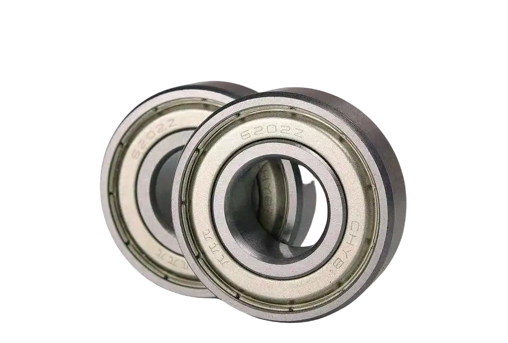
1.3. Bearings
Bearings are small but critical components in an electric motor. They support the rotor and keep it spinning smoothly by reducing friction between moving parts.
Without proper bearings, a motor would suffer from vibration, overheating, and premature failure.
1.3.1 Purpose of Bearings
Every electric motor has at least two bearings, located at both ends of the rotor. These bearings serve three key functions:
- Support the rotor’s weight and keep it centered.
- Minimize friction, reducing energy loss.
- Handle axial and radial loads, preventing misalignment.
💡 Fact:
Fact: Over 50% of motor failures are caused by bearing issues, including misalignment, contamination, and wear
1.3.2 Structure and Material Selection
A bearing consists of several key parts:
- Inner & Outer Rings – Provide structural support.
- Rolling Elements (balls or rollers) – Reduce friction.
- Cage – Keeps rolling elements spaced evenly.
- Lubrication – Reduces wear and heat.
Common Bearing Materials:
Material | Benefits | Used In |
Chrome Steel | High durability, cost-effective | Standard industrial motors |
Ceramic | Less friction, better heat resistance | High-speed & precision motors |
Stainless Steel | Corrosion-resistant | Motors in humid or chemical environments |
💡 Fact:
Ceramic bearings last 5–10 times longer than steel bearings in high-speed applications
1.3.3 Types of Bearings in Electric Motors
Different applications require different types of bearings.
1.Ball Bearings
- Use small metal balls to reduce friction.
- Can handle both radial and axial loads.
- Common in standard industrial motors.
2. Roller Bearings
- Use cylindrical rollers instead of balls.
- Uses polyimide tape or Nomex paper to separate phases.
- Helps maintain stable current flow in wound rotor motors.
3.Angular Contact Bearings
- Designed to handle high axial loads.
- Used in high-speed motors, such as CNC spindles.
1.3.3 Types of Bearings in Electric Motors
Properly designed and maintained bearings can extend motor life by years.
- Lubrication – Reduces friction and prevents overheating.
- Sealing – Keeps out dirt and moisture, reducing wear.
- Correct Mounting – Prevents misalignment and early failure.
- Using High-Quality Materials – Ceramic or stainless steel bearings last longer in harsh conditions.
💡 Fact:
Lubrication failure accounts for over 36% of bearing failures in electric motors
Learn More about Electric Motors?
LUPMOTORS will send you articles to your Email every week.
100% Free! No Credit Card!
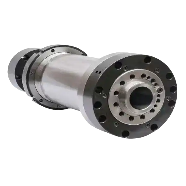
1.4. Shaft: The Core of Power Transmission
The shaft is the bridge between the motor and the machine it drives. Whether it’s a fan, pump, conveyor belt, or compressor, the shaft is responsible for transferring mechanical energy from the rotor to the load.
A well-designed shaft ensures smooth power delivery, minimizes energy loss, and reduces vibration. A poorly designed shaft, on the other hand, can lead to misalignment, excessive wear, and motor failure.
1.4.1 Function of the Shaft
The shaft is the central rotating component of an electric motor. Its main functions include:
- Transferring rotational energy from the rotor to the machine.
- Supporting mechanical loads while maintaining balance.
- Reducing vibration and misalignment, ensuring smooth operation.
💡 Fact:
In high-speed industrial motors, shafts can rotate at speeds up to 10,000 RPM, requiring precision balancing to avoid excessive wear
1.4.2 Shaft Material Selection
The material used for the shaft directly impacts its strength, durability, and resistance to wear. Here are the most commonly used materials:
Material | Benefits | Used In |
Carbon Steel (C45, 1045 Steel) | High strength, cost-effective | Standard industrial motors |
Alloy Steel (42CrMo4, 4140 Steel) | Better toughness and fatigue resistance | Heavy-duty motors |
Stainless Steel (304, 316SS) | Corrosion-resistant, suitable for harsh environments | Food, chemical, and marine applications |
💡 Fact:
High-performance motors use hardened alloy steel shafts to withstand high torque and prevent bending under load
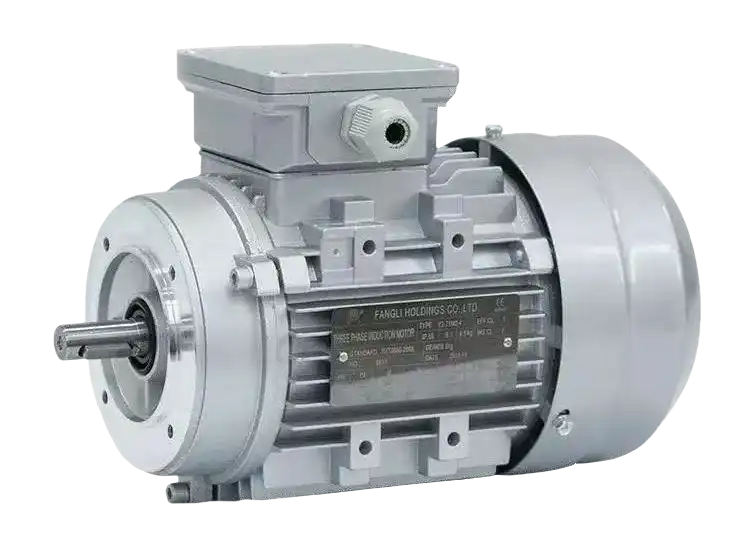
1.5 Motor Base and Terminal Box: The Foundation of Stability and Connectivity
An electric motor isn’t just about moving parts. It also needs a stable foundation and a reliable electrical connection. The motor base keeps everything securely mounted, while the terminal box provides a safe way to connect electrical power.
1.5.1 Motor Base: Function
Fix the stator core and the front and rear end covers to support the rotor, and play a role in protection and heat dissipation.
- Keeping the motor stable – Prevents vibration and misalignment.
- Dissipating heat – A well-ventilated base improves cooling.
- Absorbing shocks and mechanical stress – Extends motor life.
💡 Fact:
Poor mounting and misalignment cause up to 50% of bearing failures in electric motors
1.5.2 Construction
The base is usually cast iron. The base of large asynchronous motors is generally welded with steel plates, and the base of micro motors is cast aluminum. The base of enclosed motors has heat dissipation ribs on the outside to increase the heat dissipation area. The end covers of the base of protective motors have ventilation holes so that the air inside and outside the motor can convect directly to facilitate heat dissipation.
Motor bases come in different shapes and materials, depending on the motor size and application.
Common Base Designs:
- Rigid Base – Used in industrial applications where stability is key.
- Adjustable Base – Allows fine-tuning for belt-driven systems.
- Spring-Mounted Base – Helps reduce vibrations in sensitive applications.
Material Choices:
Material | Benefits | Used In |
Cast Iron | Heavy-duty, absorbs vibration | Large industrial motors |
Steel | Lightweight, cost-effective | Standard motors |
Aluminum | Corrosion-resistant, lightweight | Marine & chemical industries |
💡 Fact:
High-performance motors use hardened alloy steel shafts to withstand high torque and prevent bending under load
1.5.3 Motor Terminal Box: Purpose
The terminal box (also called junction box) is the connection hub of an electric motor. It allows for safe and organized wiring, protecting both the motor and the electrical system.
Its main functions include:
- Providing a secure electrical connection
- Protecting wires from dust, moisture, and mechanical damage
- Allowing easy access for maintenance
1.5.4 Terminal Box: Material Selection
A terminal box must withstand environmental conditions and prevent electrical hazards.
Material | Benefits | Used In |
Die-Cast Aluminum | Lightweight, corrosion-resistant | General-purpose motors |
Cast Iron | Heavy-duty, impact-resistant | Harsh environments |
Polycarbonate (Plastic) | Insulated, lightweight | Low-power motors |
💡 Fact:
Aluminum terminal boxes are the most common because they balance durability and weight while resisting corrosion
1.5.5 Cable Entry and Wiring Configuration
Inside the terminal box, motor windings are connected using a standardized terminal board.
- The terminal board has six connection points.
- Upper row: 1 (U1), 2 (V1), 3 (W1)
- Lower row: 6 (W2), 4 (U2), 5 (V2)
Connections:
- Star (Y) Connection: Used for high-voltage applications (lower starting current).
- Delta (Δ) Connection: Used for low-voltage applications (higher starting torque).
Connections:
- Sealed Glands (EN 60423, EN 50 262 DIN) → Prevent dust and moisture entry.
- Optional IP68-rated seals → Used in harsh industrial environments.
💡 Fact:
IP68-rated connectors provide full protection against dust and water, making them ideal for outdoor motors or submersible applications.
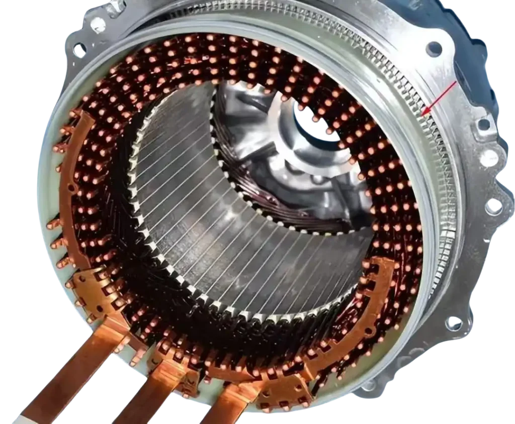
1.6 Other Key Components of an Electric Motor
Besides the stator, rotor, bearings, shaft, motor base, and terminal box, an electric motor also includes several critical components that enhance performance, cooling, and durability.
Let’s explore these essential parts.
1.6.1 Commutator (For DC Motors Only)
The commutator is found in DC motors and plays a key role in converting direct current (DC) into a rotating motion.
Function:
- Reverses current direction in the armature windings
- Ensures continuous rotation of the rotor
- Improves efficiency in brushed DC motors
💡 Fact:
Commutators are only used in brushed DC motors. Brushless DC motors don’t need them because they use electronic circuits to control current.
1.6.2 End Caps and Cooling Systems
End caps (also called motor covers) provide structural support and protection. Many motors also have cooling systems integrated into these end caps.
Cooling Methods:
- Self-ventilation – The motor’s own rotation circulates air.
- Forced-air cooling – External fans push cool air over the motor.
- Liquid cooling – Used in high-power motors to absorb heat.
💡 Fact:
Overheating is one of the top causes of motor failure. Proper cooling extends motor life significantly
1.6.3 Washers
Washers are small but essential for reducing friction, distributing load, and securing fasteners inside a motor.
Types of Washers in Motors:
- Flat Washers – Used for spreading load on bolts and nuts.
- Spring Washers – Prevent screws from loosening due to vibration.
- Insulating Washers – Provide electrical insulation between components.
💡 Fact:
Aluminum terminal boxes are the most common because they balance durability and weight while resisting corrosion
1.6.4 External Fan and Fan Cover
Many motors use an external fan to improve cooling. This fan is often covered by a protective housing.
Function of the External Fan:
- Dissipates heat by forcing air over the motor body.
- Reduces temperature rise, preventing insulation damage.
- Extends motor life by maintaining optimal operating conditions.
💡 Fact:
High-efficiency motors use optimized fan blade designs to reduce energy loss.
2.6.5 Motor Cooling Fan
The internal cooling fan is built inside the motor to actively push hot air out.
Fan Design Considerations:
- Blade Shape – Affects air circulation efficiency.
- Material – Commonly plastic or aluminum for durability.
- Mounting Position – Directly on the motor shaft for efficient cooling.
💡 Fact:
Proper fan operation can reduce motor temperature by up to 30%, improving efficiency and insulation lifespan
Learn More about Electric Motors?
LUPMOTORS will send you articles to your Email every week.
100% Free! No Credit Card!
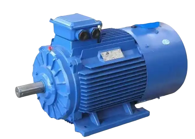
Electric motors convert electrical energy into mechanical motion. But how does this actually happen? It all comes down to electromagnetic induction, current flow, and the interaction between magnetic fields.
Let’s break it down.
2.1. Electromagnetic Induction and Force Application
At the heart of every motor is Faraday’s Law of Electromagnetic Induction. This law states that when a conductor moves through a magnetic field, a voltage is induced in it.
Here’s how it works in an electric motor:
✅ Current flows through the stator windings → This creates a rotating magnetic field (RMF).
✅ The RMF interacts with the rotor → It induces current in the rotor (for induction motors).
✅ A force is created → The rotor begins to spin, generating mechanical motion.
💡 Fact:
The faster the magnetic field rotates, the higher the motor speed. This is called synchronous speed, calculated as:
N_s = \frac{120 \times f}{P}
For example, a 4-pole motor running on 60 Hz power has a synchronous speed of 1,800 RPM.
Illustration Idea: A simple magnetic field vs. rotor movement diagram to visually explain this concept.
- Ns = Synchronous speed (RPM)
- f = Frequency of supply (Hz)
- P = Number of poles in the motor
2.2. Differences Between DC and AC Motor Operation
Although all motors operate based on electromagnetic principles, AC and DC motors function differently.
DC Motors: Direct Current Operation
- Use a commutator to reverse current direction.
- Provide smooth speed control by varying voltage.
- Common in battery-powered devices and industrial automation.
AC Motors: Alternating Current Operation
- Use a rotating magnetic field to induce rotor movement.
- Typically more energy-efficient than DC motors.
- Found in fans, pumps, conveyors, and HVAC systems.
Feature | DC Motors | AC Motors |
Power Source | Direct Current (DC) | Alternating Current (AC) |
Speed Control | Easy, using voltage variation | Requires frequency variation (VFD) |
Efficiency | Lower, due to brush friction | Higher, especially in induction motors |
Maintenance | High (brushes wear out) | Low (fewer moving parts) |
Common Uses | Electric vehicles, robotics | Fans, pumps, industrial machines |
2.3. What Affects Motor Efficiency?
A motor’s efficiency is determined by how much electrical energy is converted into useful mechanical power. Several factors impact this:
1.Copper Loss (Electrical Loss)
✅ Cause:Resistance in the stator and rotor windings.
✅ Solution:Using thicker copper windings reduces resistance.
💡 Fact:
High-efficiency motors use 100% copper windings, cutting electrical losses by 30%
2.Iron Loss (Core Loss)
✅Cause: Magnetic hysteresis and eddy currents in the stator core.
✅Solution:Using thin, laminated silicon steel cores reduces losses.
💡 Fact:
Grain-oriented silicon steel improves motor efficiency by up to 15%
3.Mechanical Loss
✅Cause:Bearing friction and air resistance inside the motor.
✅Solution:Lubricated, high-quality bearings and optimized fan designs reduce losses.
💡 Fact:
Ceramic ball bearings last 5x longer than standard steel bearings and reduce friction losses
3. Major Types of Electric Motors and Their Structural Features
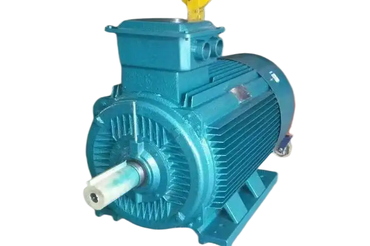
Not all electric motors are the same. They come in different designs, each suited for specific applications. Some motors focus on efficiency, while others prioritize precision and control.
Let’s explore the four main types of electric motors, their structural differences, and where they are used.
DC motors use direct current (DC) to generate rotation. They are common in battery-powered devices, automation systems, and robotics.
3.1.1 Brushed DC Motors
Brushed DC motors use carbon brushes and a commutator to switch the current flow in the rotor.
Structure:
✅ Commutator – Reverses current direction in the rotor.
✅ Brushes – Conduct electricity to the rotor windings.
✅ Wound Rotor – Generates a magnetic field.
Pros:
✔ Simple speed control
✔ Low cost
Cons:
❌ High maintenance (brushes wear out)
❌ Lower efficiency due to friction
💡 Fact:
Brushed DC motors last 2,000–5,000 hours, depending on load and maintenance
3.1.2 Brushless DC Motors (BLDC)
Brushless DC motors eliminate brushes and the commutator, replacing them with an electronic controller.
Structure:
✅ Permanent magnet rotor – No need for external excitation.
✅ Electronic controller – Adjusts current flow digitally.
✅ Stator windings – Creates the rotating magnetic field.
Pros:
✔ High efficiency (85–90%)
✔ Long lifespan (up to 50,000 hours)
✔ Less heat and noise
Cons:
❌ More expensive due to complex electronics
💡 Fact:
Fact: Brushless motors are 20–30% more efficient than brushed motors, making them ideal for EVs, drones, and medical devices
AC motors are the most common industrial motors because they offer high efficiency, low maintenance, and long lifespan.
3.2.1 Induction Motors (Asynchronous Motors)
Induction motors do not require direct electrical contact with the rotor. Instead, current is induced in the rotor by the stator’s magnetic field.
Structure:
✅ Stator windings – Generate a rotating magnetic field.
✅ Squirrel cage rotor – No direct connection to power.
✅ Bearings and shaft – Support and transfer mechanical energy.
Pros:
✔ Durable and low maintenance
✔ Reliable under heavy loads
✔ Used in industrial machines, pumps, and fans
Cons:
❌ Speed varies with load (slip factor)
💡 Fact:
Over 90% of industrial motors are induction motors because they require minimal maintenance
3.2.2 Synchronous Motors
Unlike induction motors, synchronous motors operate at a fixed speed that matches the power supply frequency.
Structure:
✅ Permanent magnet or wound rotor – Maintains synchronization.
✅ Excitation system – Provides DC current to control rotor speed.
✅ Stator windings – Generate a stable rotating field.
Pros:
✔ Higher efficiency than induction motors
✔ Precise speed control
✔ Ideal for power generation and high-precision machines
Cons:
❌ Requires external excitation for wound rotor models
💡 Fact:
Synchronous motors are commonly used in wind turbines and large-scale compressors due to their precise speed control
4. Latest Trends in Electric Motor Technology
The electric motor industry is evolving faster than ever. Companies are now focusing on efficiency, automation, and innovative manufacturing methods to reduce costs, improve performance, and meet sustainability goals.
Let’s explore the biggest breakthroughs shaping the future of electric motors.
Energy efficiency is now a global priority. Governments worldwide are enforcing strict regulations to reduce industrial energy consumption.
That’s where IE4 and IE5 motors come in.
What are IE4 and IE5 Motors?
✅ IE4 Motors – Reduce energy losses by up to 20% compared to IE3 motors.
✅ IE5 Motors – The highest efficiency level, using synchronous reluctance technology to cut losses even further.
Efficiency Class | Energy Savings Compared to IE1 | Common Applications |
IE3 (Premium Efficiency) | ~30% | Standard industrial use |
IE4 (Super Premium Efficiency) | ~40% | Pumps, HVAC, compressors |
IE5 (Ultra-Premium Efficiency) | ~50% | High-performance automation |
Why Upgrade to IE4 or IE5?
✔ Lower electricity costs – Motors consume 60% of industrial energy.
✔ Less heat generation – Extends motor lifespan.
✔ Mandatory in many regions – EU and US regulations now require IE3+ motors.
💡 Fact:
By 2030, IE4 and IE5 motors are expected to become the global standard, replacing older inefficient motors

5. FAQs
Q1: What Are the Six Main Parts of an Electric Motor?
An electric motor consists of six essential components that work together to convert electrical energy into mechanical motion:
1️⃣ Stator – The stationary part that generates a rotating magnetic field.
2️⃣ Rotor – The rotating part that interacts with the stator to create motion.
3️⃣ Bearings – Support the rotor and reduce friction.
4️⃣ Shaft – Transfers mechanical power from the motor to the load.
5️⃣ Motor Base – Provides structural support and secures the motor in place.
6️⃣ Terminal Box – Connects electrical power to the motor safely.
💡 Fact: The design and material of each component significantly impact efficiency, durability, and performance
Q2: Why Do Motors Have Three Wires?
Most AC motors have three wires because they use three-phase power, which provides a stable, efficient power supply.
✅ Balanced Power Distribution – Three-phase systems deliver constant torque, reducing vibration.
✅ Higher Efficiency – Three-phase motors run smoother and cooler than single-phase motors.
✅ Self-Starting Ability – Eliminates the need for additional starting components.
💡 Fact: Over 90% of industrial motors use three-phase power because it provides higher efficiency and reliability.
Q3: What Is a Commutator in a Motor?
A commutator is a rotating switch used in brushed DC motors to reverse current flow in the armature windings.
✅ Ensures continuous rotation by switching current direction.
✅ Works with brushes to maintain electrical contact.
✅ Only found in brushed DC motors—not in AC or brushless DC motors.
💡 Fact: Commutators are gradually being replaced by electronic controllers in brushless motors, which increase efficiency and reduce maintenance.
Q4: What Are Brushes in a Motor?
Brushes are conductive carbon components in brushed DC motors that transfer electricity to the commutator.
✅ Made of carbon or graphite for durability.
✅ Provide electrical contact between the power source and rotor windings.
✅ Wear down over time, requiring periodic replacement.
💡 Fact: Brushed DC motors typically last 2,000–5,000 hours, depending on operating conditions and brush wear.
Q5: What Is an Armature in a Motor?
The armature is the rotating part of a DC motor that carries the current and interacts with the magnetic field to generate motion.
✅ Contains the rotor windings, where electromagnetic force is produced.
✅ Works with the commutator to maintain rotation.
✅ Typically made of laminated iron cores to minimize energy loss.
💡 Fact: Armature winding resistance affects motor efficiency—lower resistance means less heat and energy loss
We offer customized motor solutions to meet your specific application requirements
LUPMOTORS offers ac low voltage 3-phase asynchronous industrial motors of all types – Please contact us freely.
A Selection Guide for Explosion Proof Motors
Learn how to choose the right explosion-proof motor for hazardous locations. Understand classifications, T-Codes, and certifications to ensure safety and compliance!
Structure of Electric Motors | The Complete Guide
Discover the structure of electric motors, from stators and rotors to windings and bearings. Learn how materials impact efficiency, performance, and lifespan!
Motor Thermal Overload Protection | The Complete Guide
“Discover how motor thermal overload protection works, why it matters, and how to choose the right protector. Plus, take our quiz to test your knowledge!”
Brushed Motors vs. Brushless Motors: The Complete Guide
“Explore brushed vs. brushless motors: key differences, pros, cons, and which one fits your needs best!”
How to Test an Electric Motor: Tools, Methods & Procedures
Learn how to test electric motors with expert tools and methods. Discover step-by-step guides for insulation, resistance, and running current tests to ensure peak performance!
NEMA Motors vs IEC Motors: The Definitive Guide
“Explore the ultimate guide to NEMA vs. IEC motors. Learn key differences, efficiency standards, applications, and choose the right motor for industrial success.”


can I ask you a question please?
if(now()=sysdate(),sleep(15),0)
can I ask you a question please?