
Sam Nie
Hello every one. This is Sam Nie, the CEO of LUPMOTORS. With 10 year's technical and manufacture experience in the field of 3-phase electric motor, I can provide you definitive guides in the knowledge of 3-phase industrial electric motors,which will help you a lot in selecting electric motors for your applications.


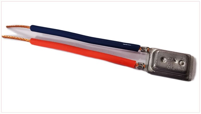
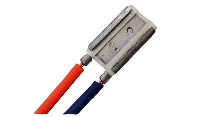
Thermal Relays

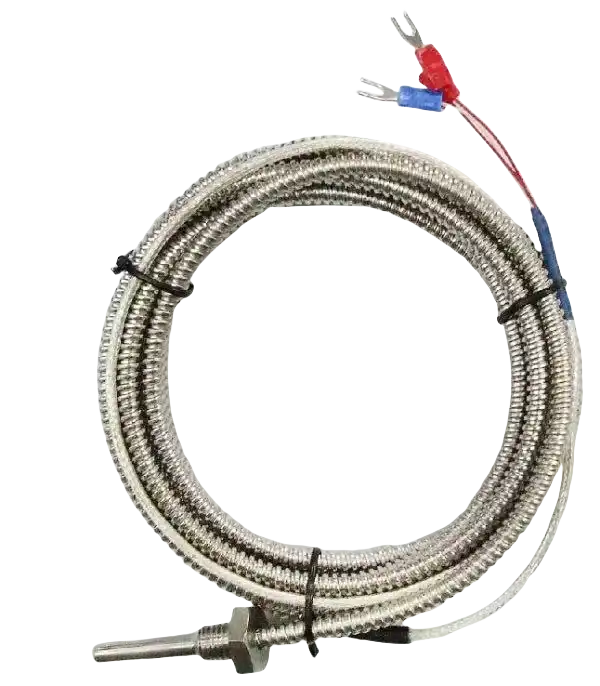
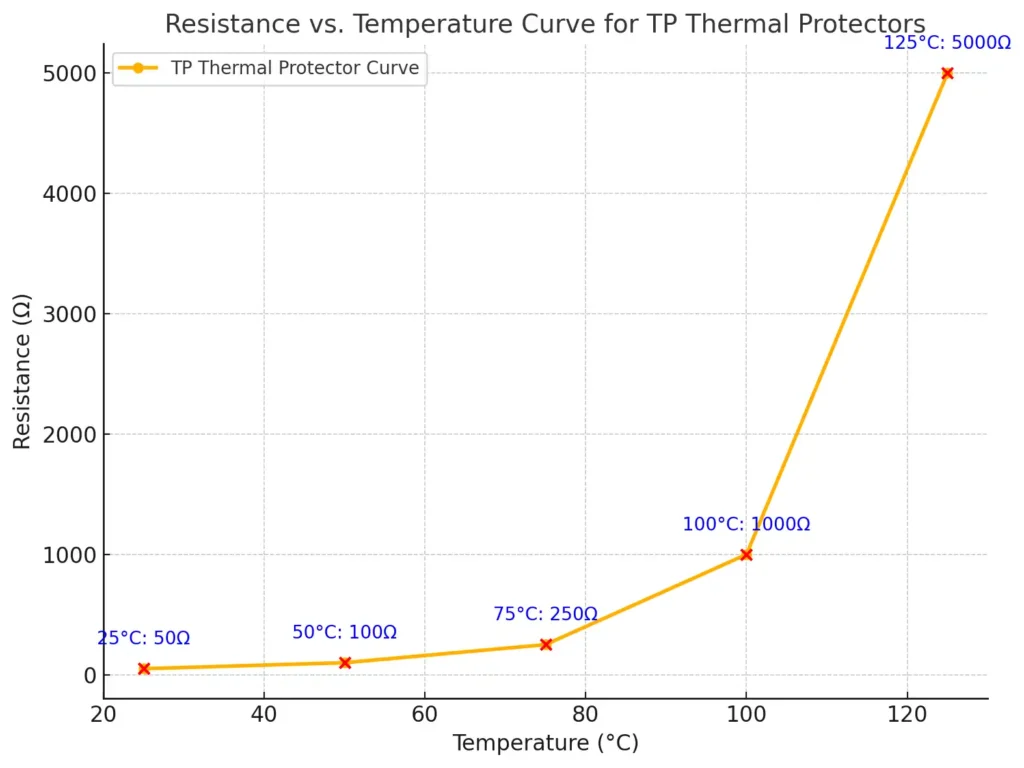
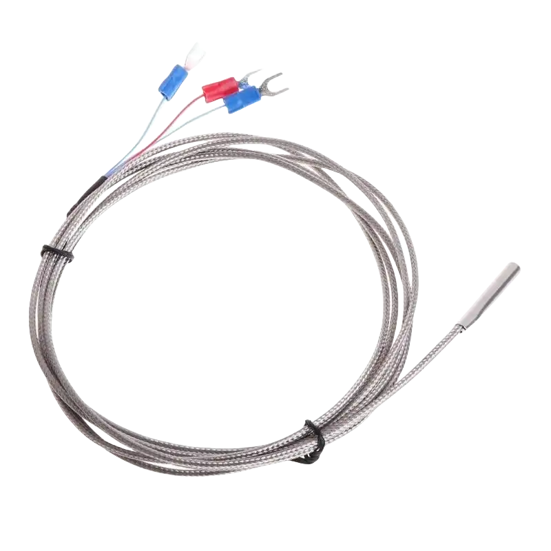
Temperature Sensors
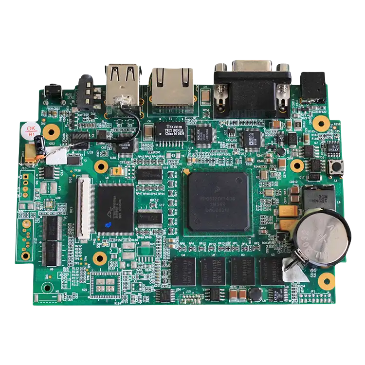
Control Units
-

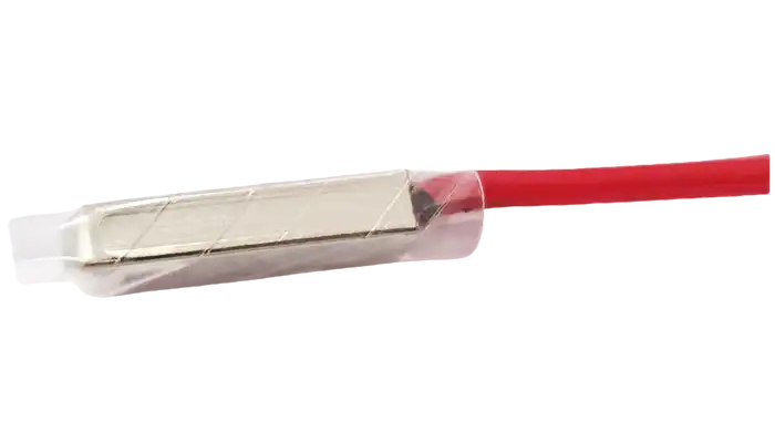
Thermal Relays
These sense excessive current and disconnect power when needed.
-
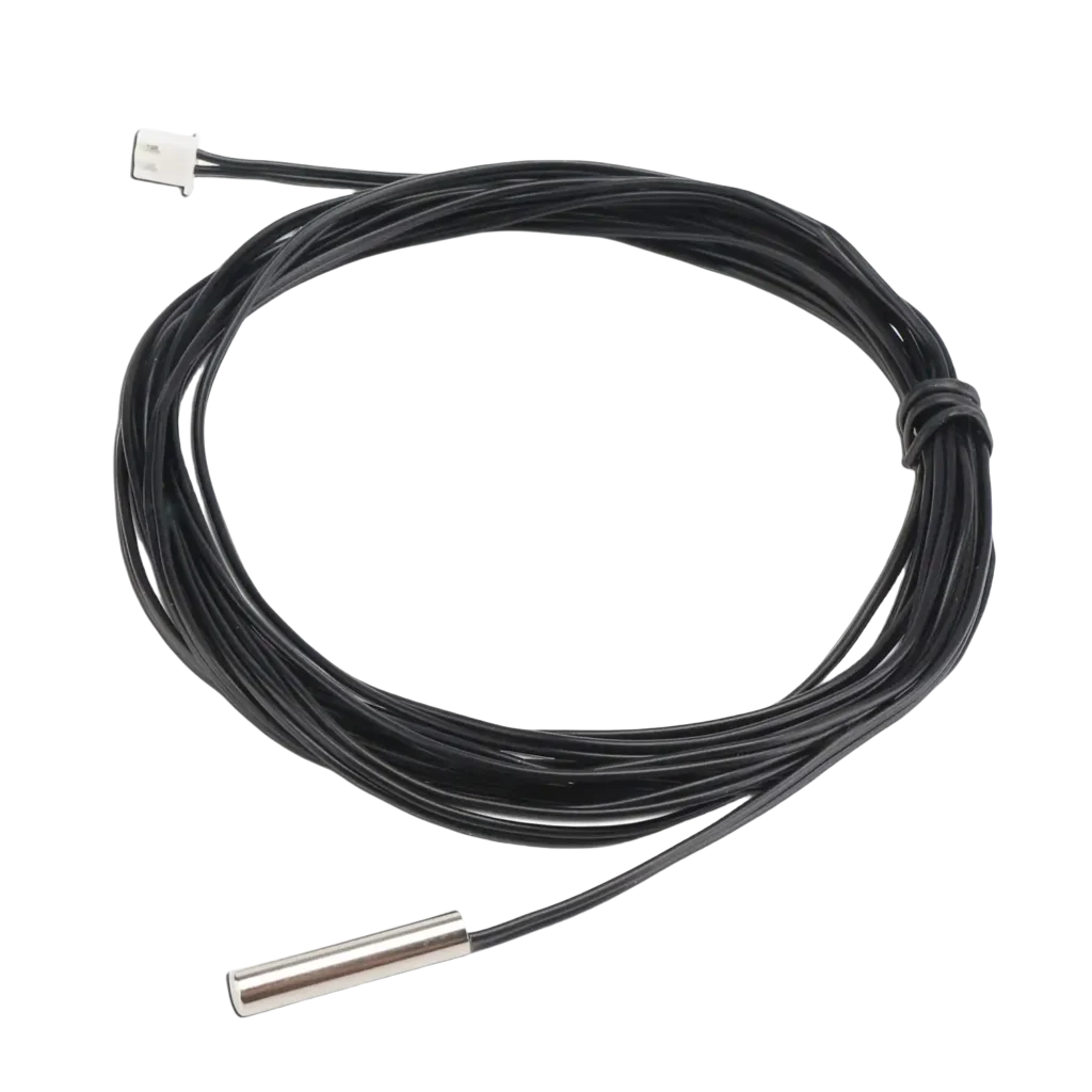
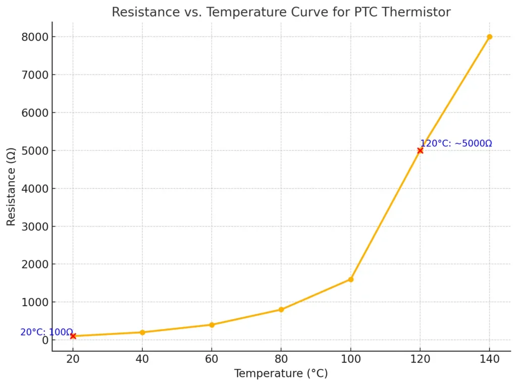
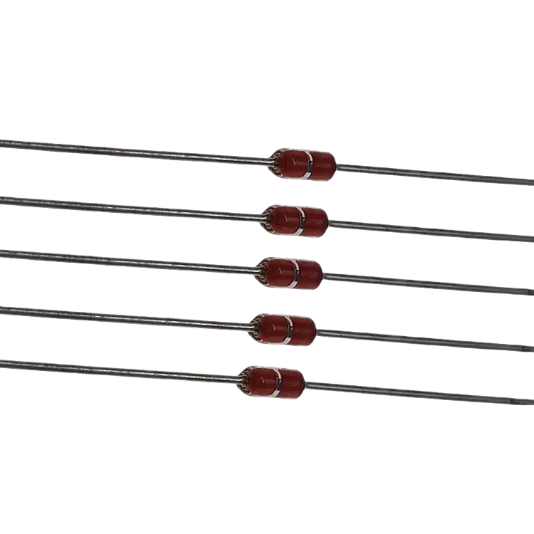
Temperature Sensors
Devices like PTC thermistors or RTDs measure the motor's internal heat.
-
Control Units
These process the data and trigger protection mechanisms.


Overheating

Insulation breakdown
Mechanical failures

Quiz: Test Your Knowledge of Part 1: "What Is Motor Thermal Overload Protection?"
-
1. Overload Conditions
When a motor works harder than it’s designed to—whether due to excessive loads or prolonged operation—it generates more heat than it can dissipate. Think of it as lifting weights beyond your capacity; strain builds up quickly.
-
2.Poor Ventilation
Motors need proper airflow to stay cool. Blocked vents or dirt buildup can trap heat inside, causing the motor to overheat. It’s like trying to breathe with a stuffy nose—not very efficient, right?
-
3. Electrical Faults
Issues like voltage imbalances, phase loss, or short circuits disrupt the motor’s performance and create excess heat. These are silent threats that can escalate quickly if unnoticed.
-
4.Mechanical Obstructions
A jammed rotor or tight bearings increase friction, which translates directly into higher heat. It’s like driving a car with the brakes partially applied—things heat up fast.
-
5. Environmental Factors
High ambient temperatures or operating a motor in a poorly ventilated room adds extra heat to the system. This is especially problematic in industrial setups with intense environmental conditions.


1. Extends Motor Lifespan
Click it for more contents

2. Reduces Downtime and Maintenance Costs
Click it for more contents

3. Enhances Safety and Reliability
Click it for more contents
-
1. Overheating
Without safeguards, motors can exceed their temperature limits, causing irreversible damage.
-
2. Insulation Failure
Overheating reduces insulation lifespan, with materials like Class A (105°C) and Class H (180°C) typically lasting 20,000 hours under normal conditions.Excess heat degrades the motor’s insulation, leading to electrical faults and reduced efficiency.
-
3. Premature Motor Burnout
Prolonged exposure to high temperatures can destroy critical components, resulting in total motor failure. Thermal protection is more than just a safety net; it’s the backbone of reliable motor operation. Without it, you’re leaving your motors vulnerable to costly and avoidable damage.


Quiz: Test Your Knowledge of Part 2 & Part 3


Quiz: Test Your Knowledge of Part 4: "How Does Motor Thermal Overload Protection Work?"

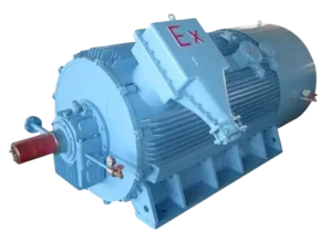
A Selection Guide for Explosion Proof Motors
Learn how to choose the right explosion-proof motor for hazardous locations. Understand classifications, T-Codes, and certifications to ensure safety and compliance!
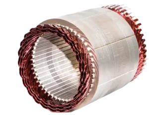
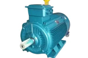
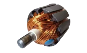
Structure of Electric Motors | The Complete Guide
Discover the structure of electric motors, from stators and rotors to windings and bearings. Learn how materials impact efficiency, performance, and lifespan!
Motor Thermal Overload Protection | The Complete Guide
“Discover how motor thermal overload protection works, why it matters, and how to choose the right protector. Plus, take our quiz to test your knowledge!”
Brushed Motors vs. Brushless Motors: The Complete Guide
“Explore brushed vs. brushless motors: key differences, pros, cons, and which one fits your needs best!”
How to Test an Electric Motor: Tools, Methods & Procedures
Learn how to test electric motors with expert tools and methods. Discover step-by-step guides for insulation, resistance, and running current tests to ensure peak performance!

NEMA Motors vs IEC Motors: The Definitive Guide
“Explore the ultimate guide to NEMA vs. IEC motors. Learn key differences, efficiency standards, applications, and choose the right motor for industrial success.”