
Sam Nie
Hello every one. This is Sam Nie, the CEO of LUPMOTORS. With 10 year's technical and manufacture experience in the field of 3-phase electric motor, I can provide you definitive guides in the knowledge of 3-phase industrial electric motors,which will help you a lot in selecting electric motors for your applications.


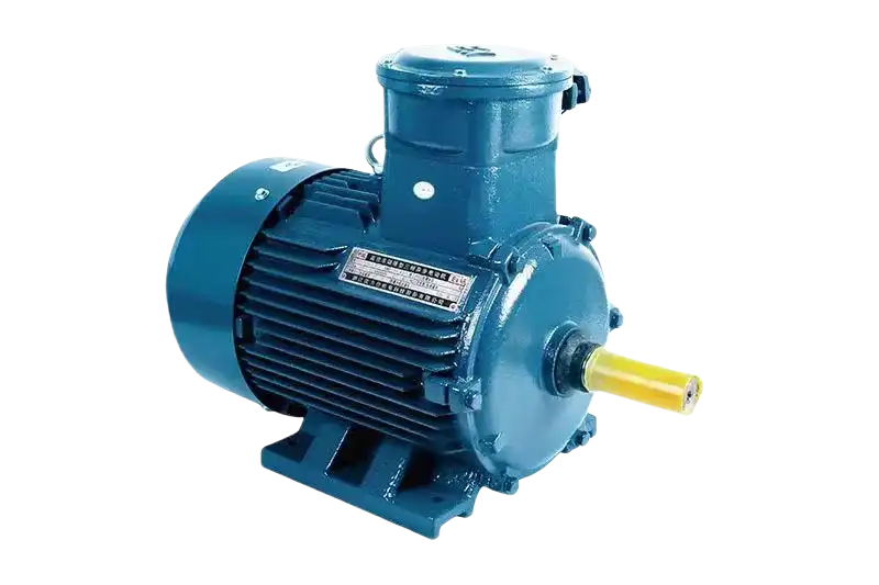
Elevators
HVAC systems
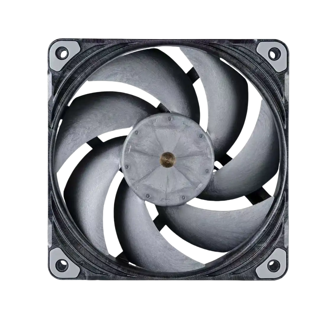
Fans

Electric cars

Power tools


-

Overheating – 55%
Overheating is the leading cause of motor failures. It results from overloading, poor ventilation, or inadequate maintenance of cooling systems.
-
Insulation Breakdown – 40%
This includes failures caused by moisture, aging, and contamination, leading to short circuits or ground faults.
-
Bearing Failures – 16%
Bearings wear out due to lack of lubrication, misalignment, or contamination. This is one of the most common mechanical failures.
-
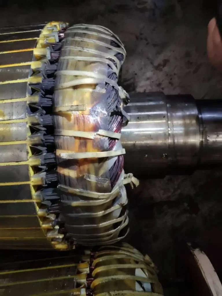
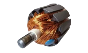
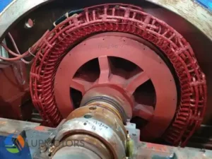
Rotor and Stator Failures – 10%
Damage to rotor bars or stator windings is less frequent but critical. These issues often stem from operational stress or manufacturing defects.
-
Electrical Imbalances – 15%
Voltage or current imbalances, often due to poor wiring or faulty power supply, strain motor components and lead to failure.


-
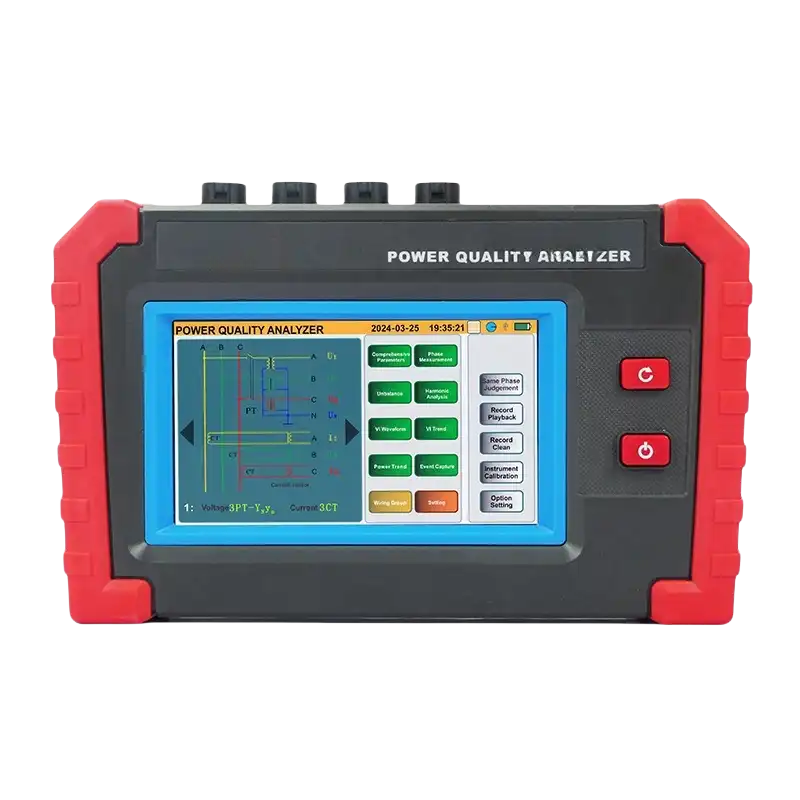
Voltage Measurement
Determines whether the motor is receiving proper voltage levels.
-
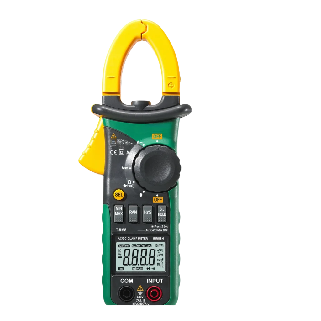
Current Measurement
Checks if the motor is drawing the correct amount of current.
-
Resistance Testing
Identifies open or short circuits in motor windings.
-
Continuity Testing
Ensures electrical paths are complete and free from breaks.


Voltage Tests
Click it for more contents

Winding Resistance
Click it for more contents

Continuity Checks
Click it for more contents

Overload Testing
Click it for more contents


Quiz: Test Your Knowledge of Part 3: "Essential Tools for Electric Motor Testing"

4.1 Insulation Resistance Test: Protecting Against Electrical Failures


-
Impact of Space Heaters:
Motors equipped with space heaters can maintain insulation resistance by keeping the windings dry. If resistance readings are borderline, running the heaters for several hours can evaporate residual moisture, improving insulation resistance before re-evaluating the motor.
-
Environmental Factors:
High humidity or condensation can drastically reduce insulation resistance, skewing test results. Always test in controlled conditions or factor environmental influences into your analysis.
-
When to Rewind:
If corrected resistance values remain below acceptable thresholds despite temperature adjustments and drying attempts, consider sending the motor for rewinding or refurbishment.
4.2 Winding Resistance Test: Ensuring Even Electrical Flow
-
Prepare the motor
Disconnect the motor from the power supply and ensure it’s fully discharged.
-
Use a digital multimeter
Set the Resistance Meter to the resistance (Ω) mode.
-
Test each winding
Measure resistance between the motor’s terminals (e.g., U-V, V-W, W-U for a three-phase motor).
-
Compare the results
The resistance values should be nearly identical for all windings. Deviations indicate problems.
4.3 Vibration Analysis: Detecting Mechanical Faults
-
Attach the sensors
Mount accelerometers to key motor points, such as the casing or shaft.
-
Run the motor
Operate the motor at normal speed while collecting vibration data.
-
Analyze the readings
Use software to compare vibration frequencies to expected baselines.
-
Interpret the results
Deviations in patterns can indicate specific faults (e.g., high-frequency spikes suggest bearing issues)
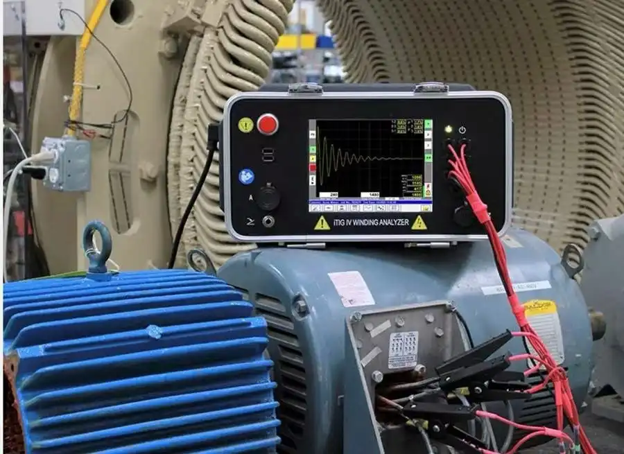
4.4 Motor Surge Test: Unveiling Electrical Weaknesses
-
Prepare the Motor
Disconnect the motor from the power supply and discharge it completely. Ensure a clean and dry environment to avoid interference from moisture.
-
Set Up the Surge Tester
Select the appropriate voltage setting based on the motor's operating voltage. For instance, if the motor operates at 460V, set the surge test voltage to approximately 1,920V (460V x 2 + 1,000V).
-
Connect the Tester
Attach the surge tester leads to the motor terminals, starting with one phase.
-
Inject the Pulse
Apply the high-voltage pulse to the phase, generating a sine wave pattern. Repeat for each phase.
-
Analyze the Results
Compare the waveforms from all phases. Consistent patterns indicate balanced windings, while distorted or mismatched waveforms reveal faults.
4.5 Motor Rotation Test: Verifying Operational Readiness
-
Prepare the motor
Ensure all safety protocols are followed and the motor is correctly connected to the power supply.
-
Power the motor
Apply voltage gradually while monitoring its startup behavior.
-
Observe the rotation
Confirm that the rotor spins in the intended direction without unusual sounds or vibrations.
-
Adjust wiring if needed
If the rotation direction is incorrect, swap two of the three-phase wires for AC motors.
4.6 Wound Rotor Motor Test: Diagnosing Specialized Motors
-
Test rotor windings
Use a digital multimeter to measure resistance between slip rings. Resistance values should be consistent across phases.
-
Check insulation
Use a megohmmeter to test insulation resistance between the rotor windings and the motor shaft
-
Inspect slip rings and brushes
Look for wear, dirt, or damage that could affect performance.
-
Test stator windings
Perform standard winding resistance and insulation tests on the stator.
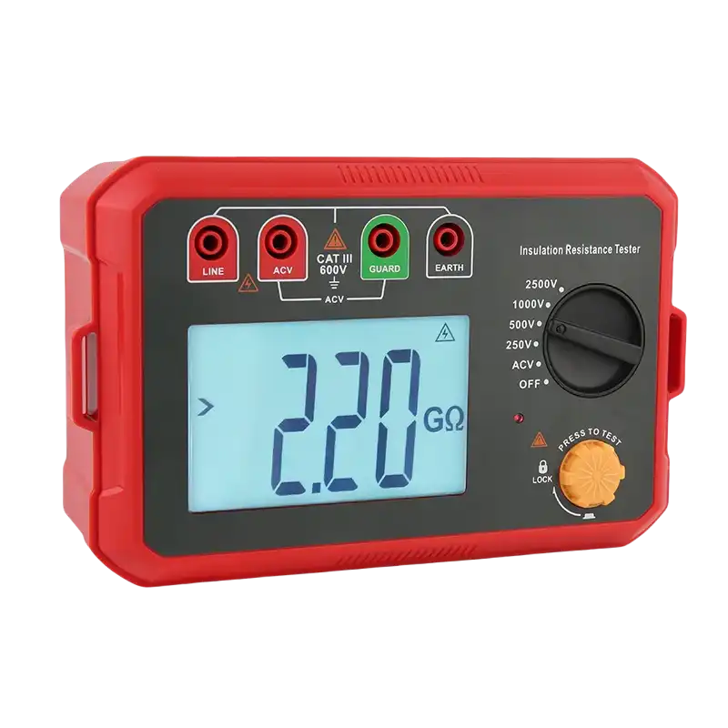
4.7 Megger Test: Insulation Resistance Under High Voltage
-
Prepare the motor
Disconnect the motor from power and discharge it completely.
-
Set up the Megger
Select the appropriate test voltage based on the motor’s rating (e.g., 500V or 1000V).
-
Connect the Megger
Attach one lead to the winding and the other to the motor’s ground or frame.
-
Run the test
Turn on the Megger and observe the resistance reading. A value above 1 MΩ is generally acceptable, but refer to manufacturer standards.
-
Record results
Consistently low resistance readings may indicate deteriorated insulation.
4.8 Polarization Index (PI) Test: Long-Term Insulation Reliability
-
Set up the Megger
Use the same equipment as for a standard insulation resistance test.
-
Run the test for 10 minutes
Measure and record the insulation resistance at the 1-minute and 10-minute marks.
-
Calculate the PI ratio
3.Divide the 10-minute resistance by the 1-minute resistance. oPI > 2.0: Good insulation. oPI between 1.0 and 2.0: Insulation may require maintenance. oPI < 1.0: Insulation is in poor condition.
-
Interpret results
A low PI value often indicates moisture or contamination within the insulation.
4.9 DC Step Voltage Test: Evaluating Gradual Insulation Strength
-
Prepare the Motor
Disconnect the motor from the power supply and discharge it completely.
-
Set up the DC step voltage tester
Configure the starting voltage (e.g., 500V) and incremental steps (e.g., 250V).
-
Apply voltage in steps
Increase the voltage incrementally, pausing to record insulation resistance at each level.
-
Monitor the readings
Look for a steady increase in resistance with higher voltages. Abrupt drops indicate weak insulation.
-
Evaluate results
Consistently high resistance suggests strong insulation, while a sharp decline points to potential issues.
4.10 Rotor Bar Test: Detecting Rotor Integrity Issues
-
Run the motor under load
Observe any unusual noise, vibration, or performance issues.
-
Use a rotor test instrument
Attach the tester to measure electromagnetic fields or use vibration analysis equipment.
-
Check for imbalances
Compare readings across the rotor to detect inconsistencies.
-
Evaluate results
Any irregular patterns typically indicate rotor bar damage.
Quiz: Test Your Knowledge of Part 4: Common Electric Motor Testing Methods

5.1.1 Standardized Testing Steps
5.1.2 Testing Procedures for Common Issues
5.1.3 Critical Tips Before and After Testing
-
Post-Test Discharge
Always discharge the motor after completing electrical tests to avoid residual voltage hazards.
-
Document Results
Record all readings and observations to track motor performance over time.
-
Evaluate Findings
Use test data to decide whether the motor requires maintenance, repair, or replacement.
5.1.4 Testing Three-Phase AC Motors: A Detailed Workflow


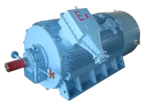
A Selection Guide for Explosion Proof Motors
Learn how to choose the right explosion-proof motor for hazardous locations. Understand classifications, T-Codes, and certifications to ensure safety and compliance!
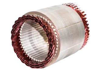
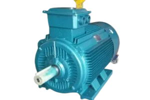
Structure of Electric Motors | The Complete Guide
Discover the structure of electric motors, from stators and rotors to windings and bearings. Learn how materials impact efficiency, performance, and lifespan!
Motor Thermal Overload Protection | The Complete Guide
“Discover how motor thermal overload protection works, why it matters, and how to choose the right protector. Plus, take our quiz to test your knowledge!”
Brushed Motors vs. Brushless Motors: The Complete Guide
“Explore brushed vs. brushless motors: key differences, pros, cons, and which one fits your needs best!”
How to Test an Electric Motor: Tools, Methods & Procedures
Learn how to test electric motors with expert tools and methods. Discover step-by-step guides for insulation, resistance, and running current tests to ensure peak performance!

NEMA Motors vs IEC Motors: The Definitive Guide
“Explore the ultimate guide to NEMA vs. IEC motors. Learn key differences, efficiency standards, applications, and choose the right motor for industrial success.”