Speed Control of Three-Phase Induction Motor | 7 Methods
03/12/2024

Sam Nie
Hello every one. This is Sam Nie, the CEO of LUPMOTORS. With 10 year's technical and manufacture experience in the field of 3-phase electric motor, I can provide you definitive guides in the knowledge of 3-phase industrial electric motors,which will help you a lot in selecting electric motors for your applications.
Controlling the speed of three-phase induction motors is necessary in industrial and commercial applications. Different applications having different motor speed requirement and most of person do not actually have an idea about how to do this properly. This lack of awareness frequently leads to operational inefficiencies and lost opportunities for optimization. When motor speeds are mismatched with application requirements, efficiency drops, power factor decreases, and energy consumption spikes. This not only inflates energy costs but also accelerates motor wear and tear, leading to higher maintenance expenses. In this guide, we’ll explore various methods of speed control for three-phase induction motors. From foundational principles to advanced techniques, you’ll gain the insights needed to enhance motor performance, save energy, and extend motor lifespan.
Table of Contents
1.Why Do We Need to Control the Speed of Three-Phase Induction Motors?
Controlling the speed of three-phase induction motors is essential for improving efficiency, precision, and adaptability in industrial and commercial operations.These motors power a vast range of applications, from manufacturing lines to HVAC systems, each requiring specific operating conditions to function optimally.

Efficiency

Precision

Adaptability
In many scenarios, a fixed-speed motor cannot meet the demands of variable workloads.
For instance, a conveyor belt might need to run slowly during delicate assembly processes but accelerate for bulk material transport. Similarly, pumps often require speed adjustments to maintain consistent pressure in systems with changing demands.
By making the speed of three-phase induction motors variable, we align motor performance with real-time requirements. This not only improves productivity but also reduces energy waste and wear on mechanical components, leading to more sustainable and cost-effective operations.

2.What Factors Determine the Speed of Three-Phase Induction Motors?
The speed of a three-phase induction motor depends on two fundamental elements: synchronous speed and slip. Understanding these concepts is essential for grasping how motor speed is controlled and optimized in various applications.

2.1 Synchronous Speed, Slip and poles

Synchronous speed
Synchronous speed (Ns) is the speed at which the magnetic field in the stator rotates. It is calculated using the formula:
$N_s = \frac{120 \times f}{P}$
- Ns= Synchronous speed (in revolutions per minute, RPM)
- f = Supply frequency (in Hertz)
- P = Number of poles in the motor
For example, if a motor has a supply frequency of 50 Hz and four poles, its synchronous speed will be:
$N_s = \frac{120 \times 50}{4} = 1500 \ \text{RPM}$
The rotor of an induction motor rotates at a speed slightly less than the synchronous speed, due to a phenomenon called slip (sss). The slip is expressed as:
$s = \frac{N_s – N_r}{N_s} \times 100$
- Nr= = Rotor speed (in RPM)
- s = Slip (in percentage)

Slip
Slip is critical for torque generation in induction motors. At startup, s=1s = 1s=1, meaning the rotor is stationary. As the motor accelerates, the slip decreases but never reaches zero during normal operation.
Synchronous speed (Ns) is the speed at which the magnetic field in the stator of a three-phase induction motor rotates. It is determined by the supply frequency (f) and the number of poles (P) in the motor. The relationship is given by the formula:
$N_s = \frac{120 \times f}{P}$
- Ns: Synchronous speed (in RPM)
- f: Supply frequency (in Hz)
- P: Number of poles in the motor
Slip is critical for torque generation in induction motors. At startup, s=1s = 1s=1, meaning the rotor is stationary. As the motor accelerates, the slip decreases but never reaches zero during normal operation.

Impact of the Number of Poles on RPM
The number of poles in a motor is a critical factor in determining its synchronous speed. Motors with fewer poles rotate faster, while motors with more poles rotate slower. For example:
A 4-pole motor at 50 Hz will have a synchronous speed of:
$N_s = \frac{120 \times 50}{4} = 1500 \ \text{RPM}$
An 8-pole motor at 50 Hz will have a synchronous speed of:
$N_s = \frac{120 \times 50}{8} = 750 \ \text{RPM}$
This inverse relationship allows motors to be designed for different speed ranges to suit various industrial applications. For high-speed tasks, motors with fewer poles are used, while low-speed operations often require motors with more poles.

Key Factors Affecting Speed
-

1.Supply Frequency (f)
Increasing or decreasing the supply frequency alters the synchronous speed. This is the principle behind frequency control methods.
-

2.Number of Poles (P)
The more poles a motor has, the lower its synchronous speed. Changing the number of poles provides a practical way to control motor speed in multi-speed motors.

Speed Control Methods Derived from These Principles
Based on the synchronous speed formula,slip concept and poles, we can categorize speed control methods into:
Stator Side Controls
Rotor Side Control Methods

3. Methods of Speed Control for Three-Phase Induction Motors
According to the principles above, we can conclude some methods to control the speed of the induction motor, categorized primarily into stator side control methods and rotor side control methods. In this section, we will explore these methods one by one.
3.1 Stator Side Control Methods
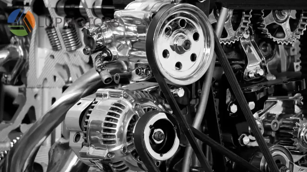
Photo: Induction Motor Transmission.
Stator side control methods focus on adjusting parameters on the stator side of a three-phase induction motor to control its speed. These methods influence the synchronous speed (Ns) by altering the supply voltage, frequency, or the number of poles. Each technique offers unique benefits and is suitable for different applications.

3.1.1. Voltage Control
Principle:
The speed of an induction motor can be adjusted by varying the supply voltage. According to the torque equation of an induction motor:
$T \propto \frac{V^2}{s}$
- T = Torque
- V = Supply voltage
- s = Slip
When the supply voltage decreases, the torque produced by the motor reduces. This impacts the motor’s ability to drive loads, causing a reduction in speed, particularly under low torque conditions. However, this method is effective only for small speed adjustments at lower loads.
Advantages
- Simple and inexpensive to implement.
- Requires minimal additional hardware.
Disadvantages:
- Limited speed control range.
- Efficiency drops significantly at reduced voltages.
- Unsuitable for high-load applications due to torque reduction.

3.1.2 Frequency Control (V/f Control)
Principle:
As the Key Factors Affecting the motor Speed we talked above, The synchronous speed of a motor is directly proportional to the supply frequency:
$N_s = \frac{120 \times f}{P}$
By varying the supply frequency (f), the synchronous speed (Ns) can be adjusted. To maintain a constant torque and prevent magnetic saturation or underfluxing, the voltage-to-frequency ratio (V/f) must remain constant. This method is widely used in variable frequency drives (VFDs).But as frequency decreases, the inductive reactance of the stator reduces, causing the motor to draw excessive current, leading to overheating and energy inefficiency. Additionally, lowering the frequency without reducing voltage results in under-fluxing, which reduces the motor’s maximum torque. This makes it less effective for handling heavy loads at low speeds. These drawbacks require careful tuning and system optimization to maintain performance and reliability.
Formula:
For a constant V/f ratio:
$\frac{V}{f} = \text{Constant}$
Suitability:
This method is ideal for applications requiring a wide range of speed control, such as conveyors, pumps, and fans.
Advantages
- Wide speed control range.
- High energy efficiency.
- Suitable for variable torque applications.
Disadvantages:
- Requires more advanced equipment, such as VFDs.
- Higher initial cost compared to voltage control.
3.1.3 Pole Changing
Principle:
The number of poles (P) in the motor determines the synchronous speed (Ns). By altering the pole configuration, the synchronous speed can be changed. This method is primarily used in squirrel cage motors, where the stator winding is designed to enable pole switching.
Formula:
$N_s = \frac{120 \times f}{P}$
For example, doubling the number of poles halves the synchronous speed, enabling dual or multi-speed operation.
By increasing the number of poles, the motor’s synchronous speed decreases. Below is a table showing how the number of poles affects synchronous speed at a standard supply frequency of 50 Hz:
| Number of Poles (P) | Synchronous Speed (N_s) |
|---|---|
| 2 | 3000 RPM |
| 4 | 1500 RPM |
| 6 | 1000 RPM |
| 8 | 750 RPM |
| 10 | 600 RPM |
This method provides fixed speed levels, making it ideal for applications such as multi-speed fans, hoists, and pumps. However, pole changing is limited to motors specifically designed for this purpose and does not offer continuous speed variation.
Use Cases:
Pole changing is commonly used in applications requiring discrete speed levels, such as multi-speed fans, hoists, and machine tools.
Advantages
- Simple and reliable for fixed speed levels.
- No significant loss in efficiency during operation.
Disadvantages:
- Limited to discrete speed changes.
- Requires special motor design with pole-changing capability.
3.2 Rotor Side Control Methods
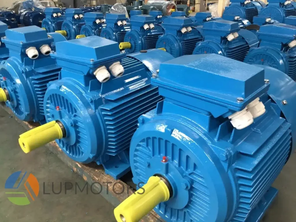
Photo: Some Electric AC Motors.
Rotor side control methods are specifically designed for slip ring induction motors, enabling speed adjustments by directly influencing the rotor circuit. Let’s explore the key methods in detail.

3.2.1 Rotor Resistance Control
Principle:
In a slip ring induction motor, external resistances can be added to the rotor circuit. This method exploits the relationship between torque, slip (sss), and resistance. By increasing the rotor resistance, the torque-speed characteristic of the motor shifts, allowing for controlled speed reduction.
Formula:
$T \propto \frac{R}{s}$
- T = Torque
- R = Rotor resistance
- s = Slip
At higher resistances, the motor develops its maximum torque (Tmax) at higher slip values, thus operating at lower speeds.
Energy Losses and Practical Implications:
Adding resistance increases energy dissipation as heat, reducing efficiency. This method is best suited for temporary or low-speed operations rather than continuous use.
This method provides fixed speed levels, making it ideal for applications such as multi-speed fans, hoists, and pumps. However, pole changing is limited to motors specifically designed for this purpose and does not offer continuous speed variation.
Use Cases:
Pole changing is commonly used in applications requiring discrete speed levels, such as multi-speed fans, hoists, and machine tools.
Advantages
- Simple and cost-effective for specific applications.
- Provides smooth and adjustable speed control.
Disadvantages:
- Energy Loss: Significant energy is lost as heat in the external resistors, reducing overall efficiency.
- Cooling Requirements: The heat generated by the resistors necessitates additional cooling systems, increasing operational costs.
- Limited to Slip Ring Motors: This method cannot be used with squirrel cage motors, restricting its applicability.
- Unsuitability for Prolonged Use: Prolonged operation at high resistance levels can lead to excessive wear and reduced motor lifespan.
- Lower Efficiency: The inherent energy losses make this method less efficient compared to modern alternatives, such as slip power recovery.
- Complexity of Maintenance: External resistors and associated components require regular maintenance, adding to the overall cost and complexity of the system.

3.2.2 Slip Power Recovery
Principle:
In this method, a portion of the slip power, which would otherwise be wasted as heat, is recovered and fed back to the supply or utilized elsewhere. This is typically achieved using a combination of power electronics and additional machinery, such as a rotary converter or static inverter.
Efficiency Benefits:
Slip power recovery systems significantly improve efficiency, especially in large motors operating under partial loads. Instead of dissipating the slip power, it is converted and reused.
Data Example:
In a 500 kW motor operating at 20% slip, slip power amounts to approximately 100 kW. A slip power recovery system can reclaim up to 95% of this power, saving up to 95 kW.
Applications
- Large compressors.
- High-capacity pumps
- Centrifugal fans in industries like cement and steel manufacturing

3.2.3 Slip Frequency EMF Injection into Rotor Circuit
Principle:
This method involves injecting an external electromotive force (EMF) of slip frequency into the rotor circuit. The injected EMF interacts with the existing rotor currents, allowing for fine-tuned control of motor speed.
Use Cases:
Ideal for applications requiring precise speed control over a wide range, such as test benches and process automation systems.
How It Works
- The injected EMF alters the slip frequency, shifting the torque-speed curve.
- Speed adjustment is achieved without changing the stator supply frequency or voltage.

3.2.4 Cascading Connection Method
Principle:
This method connects the rotor circuit of one motor to the stator of another auxiliary motor. The power from the rotor of the primary motor is utilized to drive the secondary motor, creating a cascading system that adjusts speed.
Applications:
Used in heavy industrial applications like rolling mills, large conveyors, and mining operations where variable speed is critical.
How It Works
- The cascading connection allows the primary motor to operate at a speed lower than its synchronous speed.
- The overall speed depends on the load shared between the two motors.
Advantages:
- Efficient for heavy-duty applications requiring significant speed reductions.
- Reduces the load on the primary motor.
Learn More about Electric Motors?
LUPMOTORS will send you articles to your Email every week.
100% Free! No Credit Card!

Case Studies: Real-Life Applications of Speed Control Methods
4.1 Implementation of V/f Control in Energy-Saving Projects
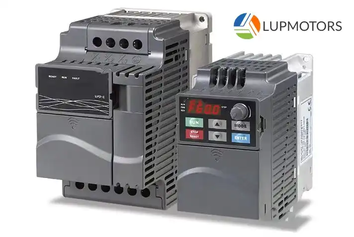
Photo: VFD.
Scenario
A manufacturing facility operating multiple conveyor belts noticed high energy costs and excessive wear on its motors due to fixed-speed operation. To address this, the facility replaced traditional starters with Variable Frequency Drives (VFDs) using V/f control.
Implementation:
- VFDs were installed on motors powering the conveyor belts.
- The V/f control method was employed to adjust motor speed based on load demands. For instance, when the conveyor carried lighter loads, the frequency and voltage were reduced proportionally, decreasing the motor's speed.
Results:

Energy Savings
Click it for more contents
The facility recorded a 30% reduction in energy consumption, equating to 150,000 kWh annually.

Cost Savings
Click it for more contents
With an average energy cost of $0.10 per kWh, the facility saved $15,000 per year.

Return on Investment (ROI)
Click it for more contents
The cost of VFD installation was recovered within two years due to energy savings and reduced maintenance costs.
4.2 Use of Slip Power Recovery in Heavy Industries

Photo: The cement factory
Scenario
A cement manufacturing plant used a 1 MW slip ring induction motor to power a large ball mill. The motor frequently operated at partial load, leading to significant energy wastage due to slip power dissipation as heat.
Implementation:
- A slip power recovery system (SPRS) was integrated into the motor's rotor circuit.
- The system captured the slip power and fed it back to the grid, reducing overall power wastage.
Results:

Energy Savings
Click it for more contents
At 15% slip, approximately 150 kW of slip power was recovered and reused.

Cost Savings
Click it for more contents
The plant saved approximately $20,000 annually in energy costs, based on $0.08 per kWh.

Efficiency Gains
Click it for more contents
Motor efficiency increased from 85% to 93%.

5. FAQs
1. Which method is the most energy-efficient for speed control?
The most energy-efficient method is frequency control (V/f control). By adjusting the supply frequency and voltage proportionally, this method minimizes energy losses while maintaining consistent torque. It’s particularly effective in applications requiring a wide speed range, such as HVAC systems and conveyor belts. Additionally, slip power recovery is highly efficient for large slip ring motors, as it recycles otherwise wasted energy back into the system or the power grid.
2.Can slip power recovery be used in small motors?
No, slip power recovery is generally not suitable for small motors. This method is designed for large slip ring induction motors where significant slip power is generated. The high cost and complexity of the required equipment, such as converters and inverters, make it impractical for small motors. Instead, other simpler methods, like V/f control or rotor resistance control, are better suited for small-scale applications.
3.How does frequency control affect torque?
Frequency control ensures a constant voltage-to-frequency ratio (V/f), which is crucial for maintaining consistent torque. If the ratio is kept constant, the motor operates within its designed magnetic flux range, ensuring optimal torque output across different speeds. However, if the frequency is reduced without proportionally reducing the voltage, magnetic saturation occurs, leading to overheating and reduced torque. Conversely, insufficient voltage at low frequencies can cause under-fluxing, resulting in a significant torque drop. This is why maintaining a constant V/f ratio is essential in frequency control.
We offer customized motor solutions to meet your specific application requirements
LUPMOTORS offers ac low voltage 3-phase asynchronous industrial motors of all types – Please contact us freely.
A Selection Guide for Explosion Proof Motors
Learn how to choose the right explosion-proof motor for hazardous locations. Understand classifications, T-Codes, and certifications to ensure safety and compliance!
Structure of Electric Motors | The Complete Guide
Discover the structure of electric motors, from stators and rotors to windings and bearings. Learn how materials impact efficiency, performance, and lifespan!
Motor Thermal Overload Protection | The Complete Guide
“Discover how motor thermal overload protection works, why it matters, and how to choose the right protector. Plus, take our quiz to test your knowledge!”
Brushed Motors vs. Brushless Motors: The Complete Guide
“Explore brushed vs. brushless motors: key differences, pros, cons, and which one fits your needs best!”
How to Test an Electric Motor: Tools, Methods & Procedures
Learn how to test electric motors with expert tools and methods. Discover step-by-step guides for insulation, resistance, and running current tests to ensure peak performance!

NEMA Motors vs IEC Motors: The Definitive Guide
“Explore the ultimate guide to NEMA vs. IEC motors. Learn key differences, efficiency standards, applications, and choose the right motor for industrial success.”

