How to Wire a 3-Phase Motor: Step-by-Step Guide & Tips
04/11/2024

Sam Nie
Hello every one. This is Sam Nie, the CEO of LUPMOTORS. With 10 year's technical and manufacture experience in the field of 3-phase electric motor, I can provide you definitive guides in the knowledge of 3-phase industrial electric motors,which will help you a lot in selecting electric motors for your applications.
When you wire a 3-phase motor, it seems complex at the beginning.
Many guys, including experienced electricians, face challenges to get the right wiring method.
The wrong wiring can lead to motor damage, low efficiency, or even complete failure.
That’s why understanding 3-phase motor wiring is very important to prevent such issues.
In this guide, I’ll tell you the step-by-step instructions to wire a 3-phase motor properly and safely.
In the end, you’ll have the confidence to wire it right and keep your motor running smoothly.
Table of Contents

1.The Preparation for Wiring
Before you start to wire a three phase motor, preparation is key. The right tools and materials can help you in safety and efficient wiring.
1.1 The Tools and Materials You Need
Here’s what we need:
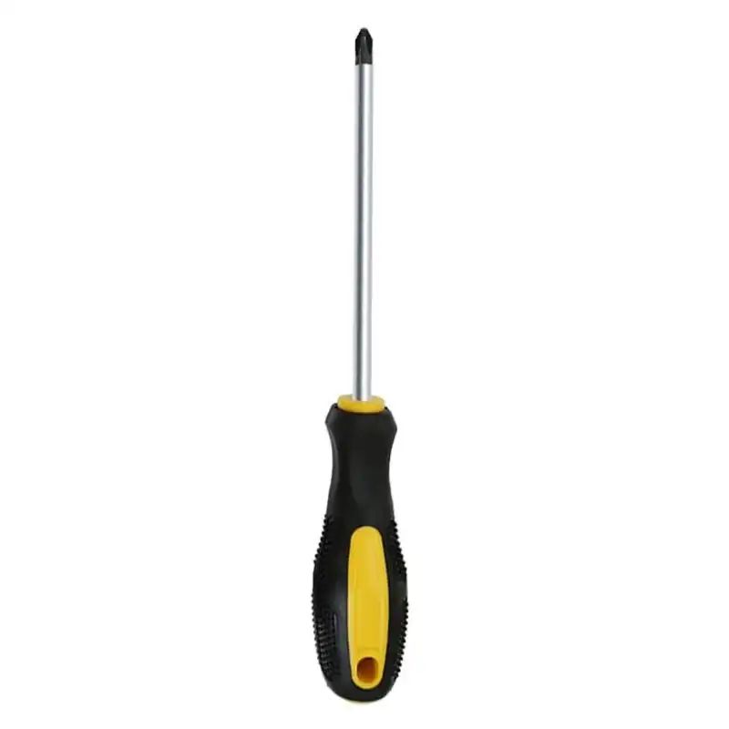
For securing terminal screws
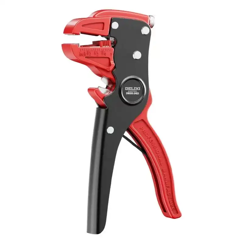
To strip insulation from wires
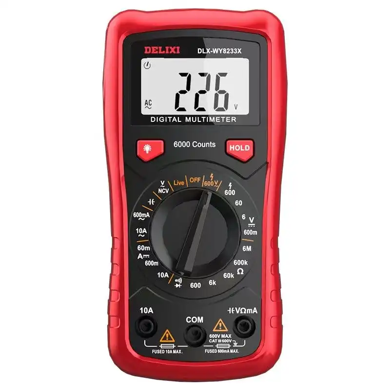
To check the safety of voltage and circuit
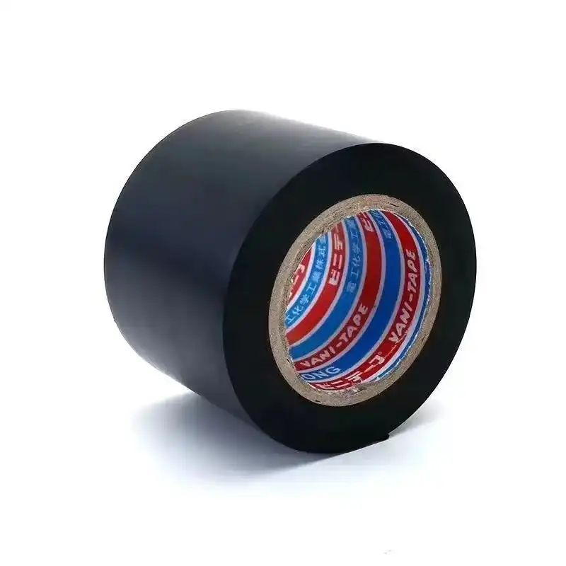
For securing and insulating connections

To keep hands and eyes protected
Tip: Make sure these tools are in good condition. Bad tools can lead to incorrect wiring or even injuries. Always inspect your equipment before use to ensure it’s up to standard.

1.2 Safety Guidelines
Safety should be first when you wire a 3-phase motor. Here’s how to ensure you stay safe during the process.
Step 1: Disconnect the Power Supply

Use Personal Protective Equipment (PPE)

Clear Your Workspace
Tip: One of the most common safety pitfalls is that assuming the power is off without verifying it. Always use a multimeter to test the circuit even after turning off the breaker. This extra step can prevent serious electrical shocks.

1.3 Basics of 3-Phase Motor Wiring
Understanding the fundamentals of 3-phase motor wiring is important for any electrical project. Let me tell you the key points and the types of connections briefly.
1.3.1 Fundamental Principles of 3-Phase Motors
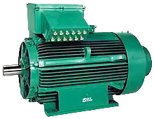
A 3-phase motor uses the three alternating currents that are out of phase with each other by 120 degrees,which provides a constant flow of power, making 3-phase motors highly efficient for industrial use. They produce a consistent torque, ideal for heavy machinery that requires smooth and reliable operation.
1.3.2 Two Types of Wiring Connections: Star (Y) and Delta (Δ)
There are 2 kinds of wiring methods for different motor conditions when you connect the 3-phase motors. Now, I will tell you the details of these 2 kinds of wiring methods.
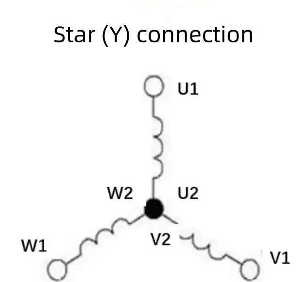

1.3.2.1 Concepts of Star (Y) Connection
In the Star (Y) connection, the ends of the three windings (U2, V2, W2) are connected together to form a neutral point. The three incoming phase lines are connected to U1, V1, and W1. This connection method is often used when:
- Lower starting currentis required.
- You need a smoother start for heavy machinery to avoid sudden surges.
When to Use: The Star connection is suitable when the motor needs to be started at a lower voltage, which helps reduce initial electrical stress on the system. It’s used in larger motors and when the application needs reduced torque at startup.
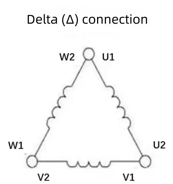

1.3.2.2 Concepts of Delta (Δ) Connection
In the Delta (Δ) connection, the end of each winding is connected to the start of the next. This means U1 is connected to W2, V1 to U2, and W1 to V2. The three incoming phase lines are connected at the three points of these connections. Delta wiring is used when:
- Full torqueis needed from startup.
- Higher starting current can be managed by the system.
When to Use: The Delta connection is more suited for applications where high torque is necessary right at the start, such as conveyor belts or heavy-load machinery.
1.3.3 Differences Explained: Star (Y) Connection vs. Delta (Δ)
When choosing between Star (Y) and Delta (Δ) connections, understanding their differences in key areas is crucial. Here’s how they compare in terms of voltage, current, torque, application, efficiency, and overall performance:
Star (Y) Connection
Delta (Δ) Connection
Star (Y) Connection
Delta (Δ) Connection
Star (Y) Connection
Delta (Δ) Connection
Star (Y) Connection
Delta (Δ) Connection
Star (Y) Connection
Delta (Δ) Connection
Star (Y) Connection
Delta (Δ) Connection

2. Step-by-Step Wiring Instructions
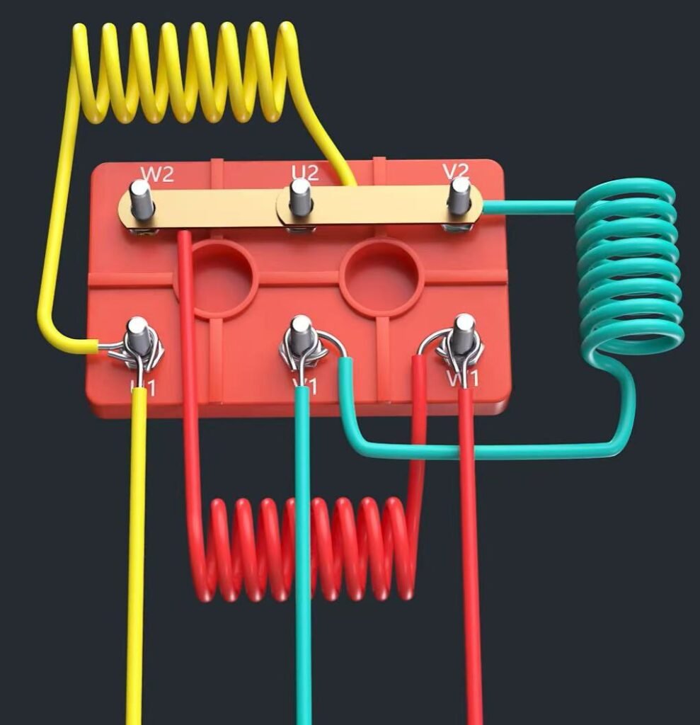
2.1 Star (Y) Connection
The Star (Y) connection is often used to start a motor with a lower initial current. This configuration reduces the initial electrical load, making it ideal for smoother startups.

1.Ensure the main power source is turned off. Use a lockout tag to secure the breaker and prevent accidental reconnection.
2.Confirm with a multimeter that there is no voltage present in the circuit. This is critical for your safety.

1.Open the motor terminal box and locate the terminals labeled U1, V1, W1, U2, V2, and W2.
2.These markings are essential for accurate wiring, so ensure you’re clear on their placement.

1.Connect the ends U2, V2, and W2 together using a connector or bus bar. This forms the neutral point of the star configuration.
2.Double-check that these connections are secure to avoid issues during operation.

1.Attach the incoming three-phase power lines to terminals U1, V1, and W1 respectively. 2.Make sure each wire is properly fastened to prevent any loose connections that could cause electrical faults.

Ensure all wire connections are tight and secure. Wrap each exposed connection with insulating tape or use protective covers to prevent accidental contact and potential short circuits.

1.Double-check the entire setup. Confirm that all connections are properly insulated and secure.
2.Use a multimeter once more to make sure there are no short circuits or issues before powering up.

1.Restore power to the motor. Run it at low speed to check the operation.
2.Monitor for any unusual noises, vibrations, or irregular performance. This can indicate potential wiring issues or faults that need addressing.
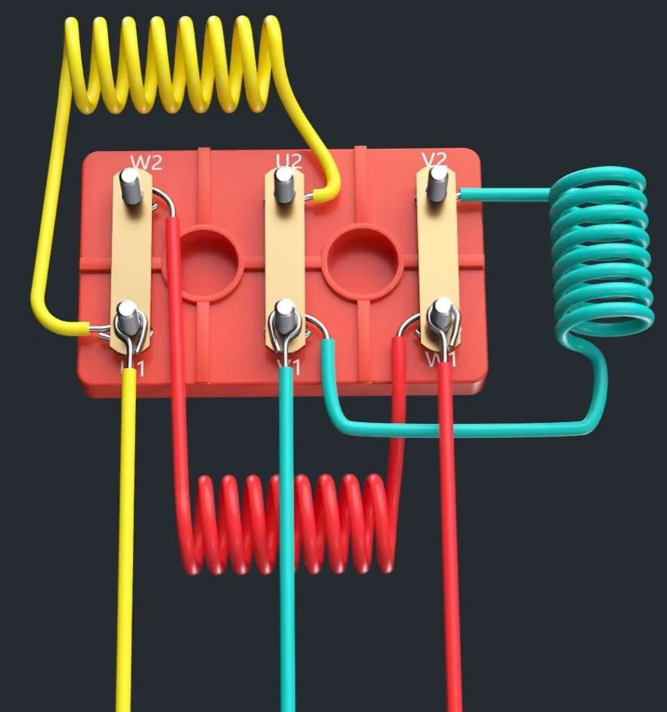
2.2 Delta (Δ) Connection
The Delta (Δ) connection is suitable for motors that need full torque from starting and can handle higher starting currents. This method ensures that the motor operates at full voltage, which maximizes power and torque output.

1.Turn off the main power supply and lock it out to ensure no one accidentally restores power.
2.Use a multimeter to verify that the circuit is closed totally. This step is very important for safety.

1.Open the motor terminal box and find the terminals labeled U1, V1, W1, U2, V2, and W2. 2.Ensure these designations are clearly visible before proceeding with the wiring.

1.Connect U1 to W2, V1 to U2, and W1 to V2. These connections form the three corners of the delta configuration.
2.Each pair of connected terminals will now create a path that forms the closed loop of the delta connection.

1.Attach the incoming three-phase power lines to the U1, V1, and W1 terminals.
2.Double-check that each power line is securely fastened to its respective terminal.

1.Ensure all terminal connections are tight and securely attached.
2.Wrap the connections with insulating tape or use protective covers to prevent accidental contact and exposure.

1.Double-check the entire wiring setup to ensure that all connections are secure and properly insulated.
2.Use a multimeter to verify that there are no short circuits or potential safety issues.

1.Turn on the power to the motor and observe its startup.
2.Listen for any unusual noises or vibrations, as these could indicate issues in the wiring or mechanical faults.
3. Common Issues and Troubleshooting
Even with careful wiring, issues can occur during motor operation. It’s important to understand the most common problems and their solutions to save our time and prevent damage to the motor.
3.1 Common Problems
Motor Not Starting
This is one of the most frequent issues and can be due to a variety of reasons.
Motor Not Starting
Possible Causes: Incorrect wiring, faulty power supply, or a broken connection within the circuit.
Unusual Noises
Unusual noises, such as humming or clicking, often indicate an electrical or mechanical problem.
Unusual Noises
Possible Causes: Loose connections, imbalanced phases, or a damaged bearing.
Overheating
Overheating can quickly damage the motor and other components.
Overheating
Possible Causes: Incorrect wiring configuration, high current draw, or an obstruction in the motor’s cooling system.
3.2 Solutions
Verify Secure Connections
2.Ensure that the wires are correctly matched to the motor terminals (e.g., U1, V1, W1).
Inspect for Circuit Breaks or Shorts
2.Examine the entire circuit to make sure there are no frayed wires, exposed connections, or other signs of damage that could lead to a short.
Check Power Supply
Balance Phases
Monitor Temperature
2.If the motor is overheating, reduce the load or check for obstructions in the cooling system.
4. Safety Guide
Ensuring safety during and after wiring a 3-phase motor is essential. Electrical work carries risks, but with careful attention and adherence to best practices, these can be minimized.
4.1 Double-Check All Wiring
- Before you turn on the power, you need to double-check every connection. Verify that all wires are securely fastened to each terminals (U1, V1, W1, etc.).
- Use a multimeter to test for continuity and confirm that there are no short circuits. This simple step can prevent major issues and ensure the motor runs safely.
- Inspect the insulation on all wires. Damaged or exposed wiring should be replaced immediately to avoid electrical hazards.
4.2 Follow Safety Protocols
- Wear Personal Protective Equipment (PPE): Always use protective gloves and safety goggles to guard against electrical shocks or debris.
- Adhere to Lockout/Tagout Procedures: Before working on the motor, lock out the main power supply and tag it to inform others that maintenance is in progress. This avoids accidental power restoration while you’re working.
- Keep Your Workspace Organized: A clutter-free environment minimizes the risk of accidental contact with live components or wires.
4.3 Final Checks Before Operation Follow Safety Protocols
- Ensure Proper Insulation: Wrap exposed wire ends with high-quality insulating tape or use protective caps.
- Inspect Phase Balance: Use a phase rotation meter to check that all phases are correctly aligned. Unbalanced phases can cause poor performance or damage to the motor.
- Test at Low Speed First: When you’re ready to power on, start the motor at a low speed and monitor for any unusual noises or movements. This test run can help identify issues before they escalate.
Safety isn’t just about protecting yourself during wiring; it’s about ensuring that the motor and its connections are secure and will operate reliably in the long period. Always follow the manufacturer’s safety guidelines and local electrical codes to maintain the highest safety standards.

5. FAQs
Can you wire a 3-phase motor wrong?
Yes, wiring a 3-phase motor incorrectly can lead to serious issues. Incorrect wiring can cause the motor to run in the wrong direction, not start at all, or suffer damage due to improper current flow. Always follow the manufacturer’s wiring diagrams and use a multimeter to verify connections before applying power.
2. How many wires go to a 3-phase motor?
A 3-phase motor typically has three main power wires that connect to the motor terminals (U1, V1, and W1). Additionally, there may be grounding wires and wires for auxiliary components, depending on the motor type and configuration.
How many connections are required at a 3-phase motor?
In general, six connections are needed within the motor terminal box: U1, V1, W1, U2, V2, and W2. These connections allow for configuring the motor in either Star (Y) or Delta (Δ) formations. However, only three power connections (U1, V1, W1) are made to the incoming power supply.
How to tell if a motor is Delta or Wye (Star)?
You can tell whether a motor is Delta or Wye by looking at its nameplate or wiring diagram. A Star (Y) connection typically has the ends of the windings connected to form a neutral point, while a Delta (Δ) connection loops the end of each winding to the start of the next. The terminal markings can also provide clues: connected U2, V2, and W2 suggest a Star configuration, whereas paired terminals like U1 to W2 indicate Delta.
Which is better, Wye or Delta?
The choice between Wye (Star) and Delta depends on the motor’s application:
- Wye (Star)is better for applications needing a soft start with reduced current, which helps to lower initial stress on the motor.
- Delta (Δ)is preferred for motors that require full torque from startup, providing higher starting current and power.
Why is a 3-phase motor cheaper than a single-phase motor?
While the initial cost of three-phase motors is generally higher, they tend to be cheaper in the long run due to their efficiency and durability. Three-phase motors consume less power and produce less wear, reducing energy bills and maintenance costs over time. This makes them more cost-effective than single-phase motors in continuous-use settings.
How to determine 3-phase Delta or Wye?
You can determine if a 3-phase motor is Delta or Wye by checking the wiring configuration in the terminal box:
- Wye (Star): The ends of the windings (U2, V2, W2) are connected together, forming a central neutral point.
- Delta (Δ): The windings are connected in a loop where U1 connects to W2, V1 to U2, and W1 to V2.
We offer customized motor solutions to meet your specific application requirements
LUPMOTORS offers ac low voltage 3-phase asynchronous industrial motors of all types – Please contact us freely.
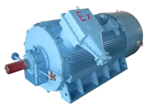
A Selection Guide for Explosion Proof Motors
Learn how to choose the right explosion-proof motor for hazardous locations. Understand classifications, T-Codes, and certifications to ensure safety and compliance!
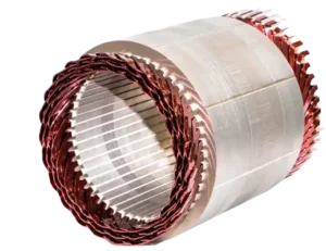
Structure of Electric Motors | The Complete Guide
Discover the structure of electric motors, from stators and rotors to windings and bearings. Learn how materials impact efficiency, performance, and lifespan!
Motor Thermal Overload Protection | The Complete Guide
“Discover how motor thermal overload protection works, why it matters, and how to choose the right protector. Plus, take our quiz to test your knowledge!”
Brushed Motors vs. Brushless Motors: The Complete Guide
“Explore brushed vs. brushless motors: key differences, pros, cons, and which one fits your needs best!”
How to Test an Electric Motor: Tools, Methods & Procedures
Learn how to test electric motors with expert tools and methods. Discover step-by-step guides for insulation, resistance, and running current tests to ensure peak performance!
NEMA Motors vs IEC Motors: The Definitive Guide
“Explore the ultimate guide to NEMA vs. IEC motors. Learn key differences, efficiency standards, applications, and choose the right motor for industrial success.”


