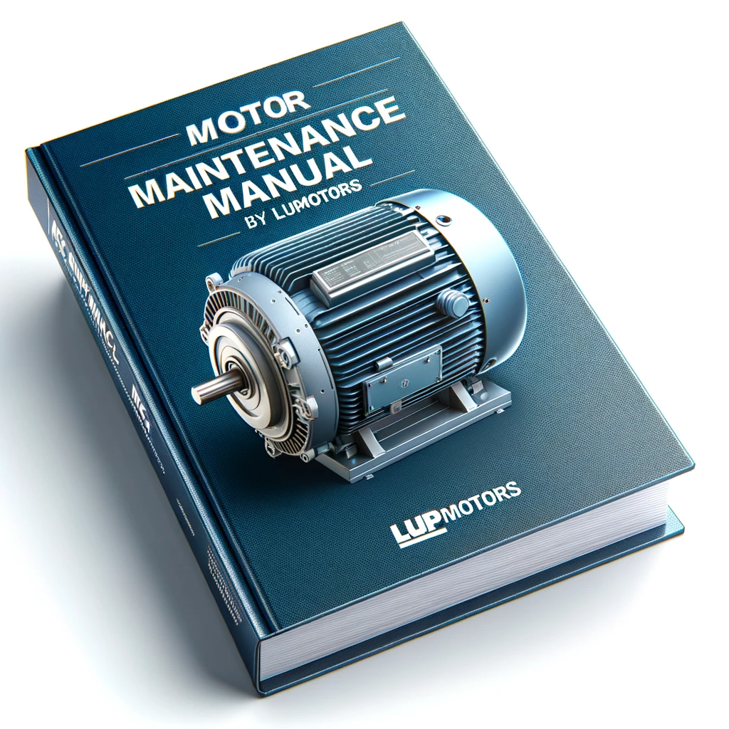
Stator vs. Rotor: Difference, Functions, Components & More
04/12/2024

Sam Nie
Hello every one. This is Sam Nie, the CEO of LUPMOTORS. With 10 year's technical and manufacture experience in the field of 3-phase electric motor, I can provide you definitive guides in the knowledge of 3-phase industrial electric motors,which will help you a lot in selecting electric motors for your applications.
The stator and rotor are the two key components of an electric motor, each playing a vital role in its operation. Together, they ensure the smooth conversion of electrical energy into mechanical motion, which powers countless devices and systems in various industries.
Understanding the differences between the stator and rotor is essential for anyone involved in motor maintenance, design, or application. Their unique functions and components determine the efficiency and reliability of the motor’s performance.
In this article, we’ll explore what stators and rotors are, their respective components, how they work, and why they matter. By the end, you’ll have a clear understanding of these essential motor parts and their importance in modern technology.
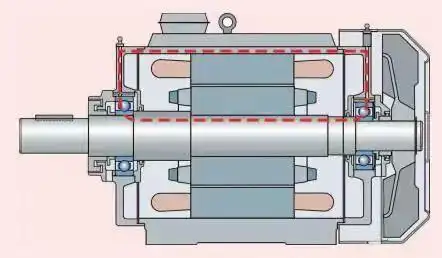
Table of Contents
1. Definition of stator and rotor of the induction motor
1.1 What Is a Stator?
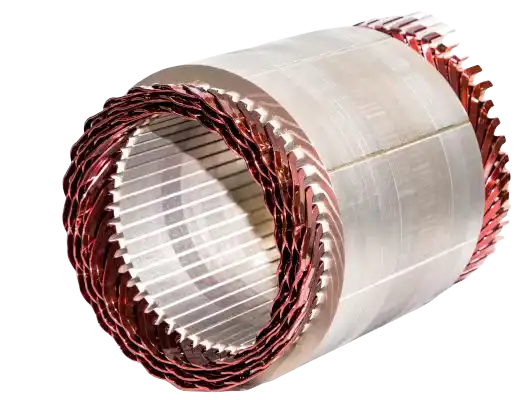
The stator is the stationary component of an electric motor, serving as the foundation for its operation. Its primary role is to generate the rotating magnetic field that interacts with the rotor to produce motion.The stator achieves this by supplying alternating current to its windings, which are strategically arranged to create a rotating magnetic field around the rotor. This electromagnetic environment is essential for inducing current in the rotor and driving its motion.
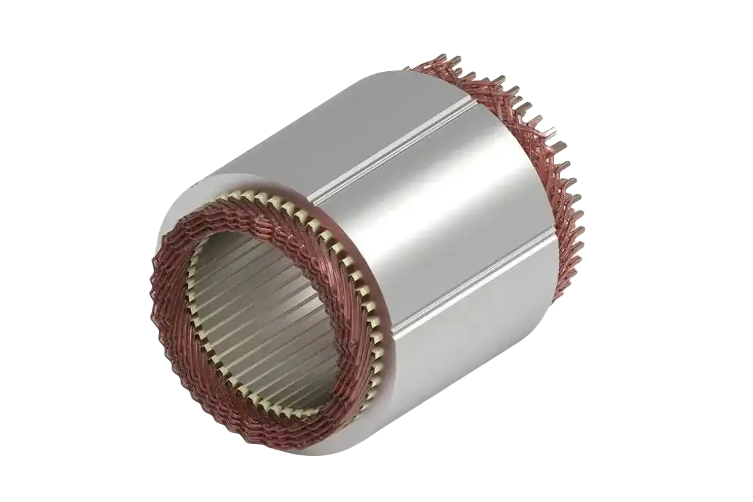
Motor Stator
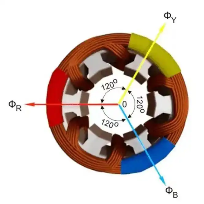
Magnetic Field
As the fixed part of the motor, the stator not only supports the dynamic operation of the rotor but also ensures stability and consistency in the motor’s performance. Its ability to maintain a precise and powerful magnetic field makes it indispensable in converting electrical energy into mechanical power.

Supports the dynamic operation of the rotor

Ensures stability and consistency in operation
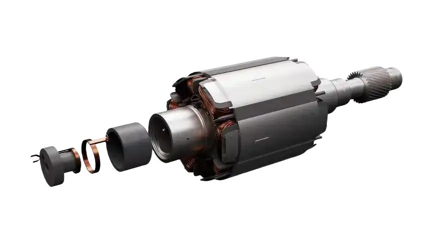
1.2 What Is a Rotor?
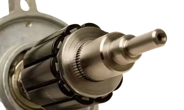
The rotor is the rotating component of an electric motor. Its primary role is to convert electrical energy into mechanical energy, enabling motion. This crucial part spins within the motor, interacting with the stator’s magnetic field to produce rotational force. As it spins within the motor, the rotor interacts with the magnetic field generated by the stator. This interaction induces an electromotive force (EMF) within the rotor’s conductive elements, such as aluminum or copper bars.This induced EMF drives the flow of current through the rotor, creating its own magnetic field.
electrical energy
mechanical energy
The resulting electromagnetic forces generate the torque needed to produce rotational motion. This motion powers mechanical systems, making the rotor a critical element in transforming electricity into usable mechanical energy.
Tip: These articles are about the definition of stator and rotor about the induction motors. So you will be very be clear about the whole definitions after you read them.
Video Resources
Tip: This video will illustrate the Principle of the stator and rotor.
2. Components of stator and rotor

2.1 Components of a Stator
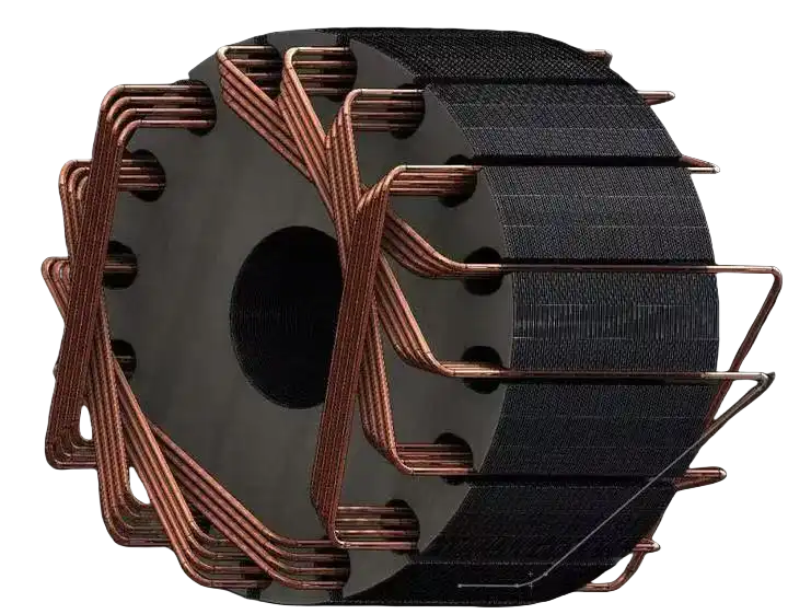
The stator comprises several critical parts that work together to create a stable magnetic field:
1.Windings
Click it for more contents
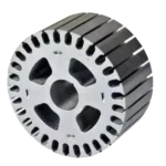
The windings consist of multiple turns of copper or aluminum wire wrapped around specific sections of the core.These wires are designed to carry electrical current, which generates the magnetic field essential for motor operation. The winding patterns and number of turns are optimized to achieve the desired electromagnetic performance.
2.Core
Click it for more contents
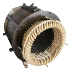
The core is constructed from thin sheets of laminated steel or iron stacked together.The material used in the core is carefully selected for its magnetic properties, ensuring it efficiently conducts the magnetic field while minimizing heat generation.
3.Insulation
Click it for more contents
Insulation materials, often made from specialized polymers or varnishes, coat the windings to prevent electrical short circuits and damage from overheating.This layer of protection ensures that the stator operates safely and reliably over its lifetime, even in high-temperature or high-stress environments.

2.2 Components of a Rotor
The rotor’s structure is designed for effective conversion of magnetic energy into mechanical motion. Its main components include:
Core
Core:
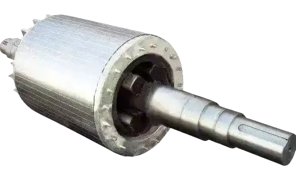
The rotor core is typically made from thin laminations of steel.The steel used in the core is specifically chosen for its magnetic permeability, ensuring it effectively supports the interaction with the stator’s magnetic field. This design optimizes torque production while minimizing heat build-up.
Conductive Bars
Conductive Bars
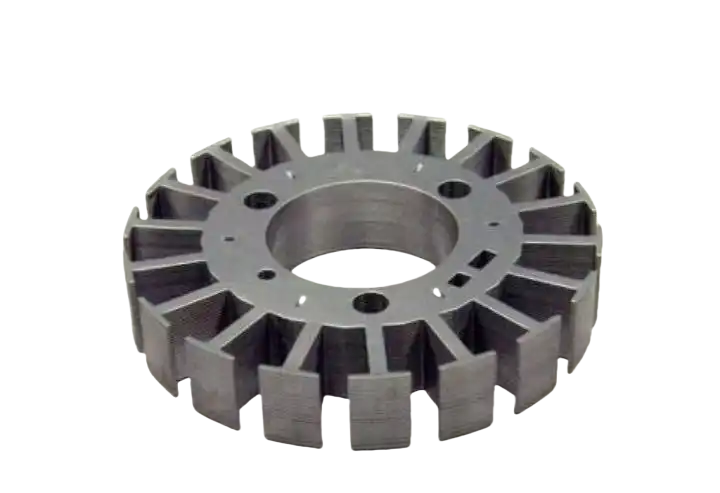
The rotor features conductive bars embedded in its core, usually made from aluminum or copper. When the stator’s magnetic field induces a current in these bars, it generates a secondary magnetic field. This field interacts with the stator’s field, producing the electromagnetic force that causes the rotor to turn.
Bearings
Conductive Bars
Bearings are located at both ends of the rotor to facilitate smooth and stable rotation. They reduce friction between the rotor and stationary motor parts, ensuring seamless motion.These components are made from durable materials like steel or ceramic to withstand high-speed operation and prolonged use.
Learn More about Electric Motors?
LUPMOTORS will send you articles to your Email every week.
100% Free! No Credit Card!
3 Types of Rotors
Rotors come in two main types: the squirrel cage rotor and the wound rotor. Each type has unique features and serves specific applications.
3.1 Squirrel Cage Rotor
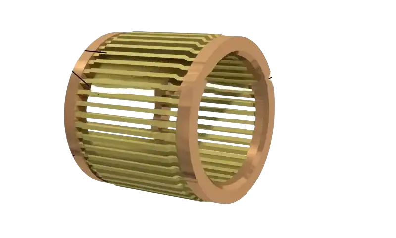
The squirrel cage rotor is the most commonly used type in induction motors. It consists of a cylindrical core with conductive bars (usually aluminum or copper) embedded in it, connected by end rings.
Key Features
- Simple, rugged construction
- Low maintenance requirements
- Ideal for general-purpose motors
Applications
- Fans
- pumps
- conveyor belts
3.2 wound Rotor
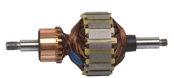
The wound rotor, also known as a slip ring rotor, has windings on its core connected to external slip rings. This design allows for variable resistance to be added during operation.
Key Features
- Allows control of starting current and torque
- More complex and requires regular maintenance
Applications
- Cranes
- hoists
- heavy-duty machinery
3.3 Differences Between Squirrel Cage and Wound Rotors
| Aspect | Squirrel Cage Rotor | Wound Rotor |
|---|---|---|
| Construction | Conductive bars with end rings | Windings with slip rings |
| Maintenance | Low | High |
| Cost | Economical | Expensive |
| Control | Fixed performance | Adjustable starting torque |
| Applications | General-purpose motors | Heavy-duty and high-torque tasks |
Tip: This article illustrate that the definition of squirrel cage rotor and wound rotor specifically. So you are going to be clear about them after you read it.

4. Functions of stator and rotor

4.1 Functions of the Stator
The stator is the fixed, immovable part of an electric motor, forming the core around which the motor’s operation revolves. Its primary function is to generate a consistent and powerful magnetic field, which is the cornerstone of motor operation.

1.Magnetic Field Generation
Click it for more contents
The stator produces the rotating magnetic field by passing alternating current (AC) through its windings. This field creates the necessary electromagnetic interaction with the rotor.
2.Energy Conversion Support
Click it for more contents
By generating a magnetic field, the stator enables the transformation of electrical energy into mechanical energy. This interaction drives the rotor into motion.

3.Structural Support
Click it for more contents
The stator also provides mechanical support and stability to the motor, ensuring the other components remain aligned and function optimally.

4.2 Functions of the Rotor
The rotor is the dynamic counterpart to the stator, designed to harness the magnetic field generated by the stator and convert it into mechanical motion.
Conversion of Magnetic Energy to Motion
The rotor responds to the stator’s magnetic field, inducing current in its conductive bars. This interaction produces the torque necessary for rotational movement.
Driving Mechanical Output
This rotation is what powers various mechanical systems, from large industrial machinery to everyday appliances like washing machines and fans.
Operational Efficiency

The rotor’s precise design ensures it can rotate smoothly and efficiently, minimizing energy loss and mechanical wear.
5.Key Differences Between Stator and Rotor
Understanding the distinctions between the stator and rotor is crucial to grasping how electric motors function. Here’s a side-by-side comparison of their key differences:
| Aspect | Stator | Rotor |
|---|---|---|
| Movement | Stationary | Rotates inside the stator |
| Magnetic Field | Creates the magnetic field | Reacts to the magnetic field |
| Components | Core (laminated steel or iron), windings (copper or aluminum), and insulation | Core, conductive bars (aluminum or copper), and bearings |
| Cooling Systems | Typically air-cooled or liquid-cooled | Primarily cooled by air movement |
| Insulation Needs | High standards to prevent electrical faults | Lesser insulation compared to stator |
Tip: These articles illustrate Key Differences Between Stator and Rotor. So you are going to be clear about them after you read it.
Video Resources
Tip: These 2 videos will illustrate the Key Differences Between Stator and Rotor of the electric motor.
6.How Stator and Rotor Work Together
The stator and rotor are designed to work in harmony, transforming electrical energy into mechanical motion. Their interaction is the heart of every electric motor’s operation.
Working Principle of the induction motors
The stator generates a magnetic field by supplying electric current to its windings. This magnetic field interacts with the rotor, inducing a current in the rotor’s conductive bars or windings. The resulting electromagnetic forces cause the rotor to rotate. This rotation drives the mechanical output of the motor, powering various applications.
Tip: This articles states the working principle of the induction motors,including the working principle of the motors, motor components such as the differences between stator and rotor. So you will be very be clear about the whole principle after you read it.
Video Resources
Tip: These 2 videos will illustrate the Working Principle of the induction motors.

7.Key Innovations of stator and rotor

7.1 Key Innovations in the Stator
The stator has seen significant advancements aimed at improving efficiency and durability:
Advanced Insulation Materials

Modern insulation materials offer superior heat resistance, enhancing the stator’s longevity and performance. These materials reduce energy loss and prevent damage from electrical stress.
Cooling Technologies

Innovations like liquid cooling systems and optimized air circulation designs have significantly improved heat dissipation. This ensures stable operation, even in high-performance motors, where overheating is a common challenge.

7.2 Key Innovations in the Rotor
Rotor technology has evolved to meet the growing demand for efficiency and sustainability:
Lightweight Materials

The use of advanced alloys and composites reduces the rotor’s weight, lowering energy consumption and enhancing motor responsiveness.
Efficiency-Driven Designs
New designs, such as optimized slot and bar arrangements, improve the rotor’s interaction with the stator’s magnetic field, minimizing energy loss and maximizing torque output.

8. FAQs
1.Can a rotor function without a stator?
No, a rotor cannot function without a stator. The rotor relies on the magnetic field generated by the stator to induce current and produce the electromagnetic forces required for rotation. Without the stator, the rotor would have no driving force to create motion.
2.What’s the lifespan of these components?
The lifespan of a stator or rotor largely depends on factors like material quality, operating conditions, and maintenance. On average:
- Stators:Can last 10-15 years or longer with proper insulation and cooling.
- Rotors:Typically have a similar lifespan, though wear on bearings may require earlier attention.
Proper care, such as regular cleaning and avoiding overloads, can significantly extend their life.
3.What happens when a stator or rotor fails?
- Stator Failure:Typically results in loss of the magnetic field, causing the motor to stop functioning. It may also lead to overheating or electrical shorts.
- Rotor Failure:Can cause irregular rotation, loss of torque, or complete motor failure due to broken conductive bars or damaged bearings.
We offer customized motor solutions to meet your specific application requirements
LUPMOTORS offers ac low voltage 3-phase asynchronous industrial motors of all types – Please contact us freely.
Synchronous Motor vs. Induction Motor: The Definitive Guide
“Discover the key differences between synchronous and induction motors. Learn about their structure, operation, advantages, and applications to make the right choice for your needs.”

AC vs. DC Electric Motors: What’s the Difference?
Discover the key differences between AC and DC motors. Learn their working principles, advantages, and real-world applications to choose the right motor for your needs.

10 Duty Cycles for Electric Motors that You Need to Know
Discover the 10 essential duty cycles for electric motors! Learn how each impacts performance, efficiency, and applications. Perfect for engineers & industries.
Stator vs. Rotor: Difference, Functions, Components & More
Discover the key differences between stator and rotor in electric motors. Learn their functions, components, applications, and innovations. Motor Stator vs. Rotor.
Speed Control of Three-Phase Induction Motor | 7 Methods
Discover effective methods for speed control of three-phase induction motors, including V/f control, pole changing, and rotor resistance control, to enhance efficiency and performance.
3-Phase AC Induction Motor | Working Principle, Definition & Types
Learn the working principle of 3-phase AC induction motors, their definition, structure, types, and real-world applications. A must-read for industrial insights!


