10 Duty Cycles for Electric Motors that You Need to Know
11/12/2024

Sam Nie
Hello every one. This is Sam Nie, the CEO of LUPMOTORS. With 10 year's technical and manufacture experience in the field of 3-phase electric motor, I can provide you definitive guides in the knowledge of 3-phase industrial electric motors,which will help you a lot in selecting electric motors for your applications.
When you think of electric motors, you might imagine them continuously humming away, powering everything from conveyor belts to cranes. But did you know motors don’t always work the same way? That’s where duty cycles come in.
In simple terms, a duty cycle is the rhythm of work and rest for a motor. It tells us how long a motor can run under specific conditions without overheating or losing efficiency. For engineers and industries, understanding duty cycles isn’t just convenient—it’s important. Different electric motor has the different duty cycle. Choosing the wrong cycle can lead to overheating, wasted energy, and even costly breakdowns.
This guide dives into 10 essential duty cycles for electric motors. We’ll be clear about some simple explanations, real-world examples, and even a few tips to make sure your motor operates at its best. Whether you’re designing a machine or troubleshooting one, this article is your shortcut to smarter motor choices. Let’s get started!
Table of Contents

1.What Are Motor Duty Cycles?
Electric motors are like people—they don’t all work the same way. Some work non-stop, while others prefer a balanced routine of work and rest. These different routines are what we call motor duty cycles.
1.1 What Exactly Is a Motor Duty Cycle?
A motor duty cycle defines the sequence of operation for a motor—its work, rest, and recovery periods. This isn’t just about theory; it’s about how efficiently and safely a motor performs its job. Choosing the right duty cycle impacts performance, saves energy, and prevents wear and tear.
1.2 Types of Working Duty
1.2.1 Duty cycles directly influence a motor's:

Performance

Efficiency

Longevity
1.2.2 Types of Working Duty
The working mode of a motor refers to the working mode of the motor under certain conditions. It can be roughly divided into three categories according to the length of the motor’s working time: continuous operation, short-time operation, and intermittent operation.
Now let’s classify these working routines:
| Duty Type | Description |
|---|---|
| Continuous Duty | Runs non-stop under rated conditions. |
| Short-Time Duty | Works briefly, then rests for cooling. |
| Intermittent Duty | Alternates between work and rest in cycles. |
-

Continuous Duty
This is like pulling a 24-hour shift without rest—tough, but efficient for certain tasks. The rated category of the motor should be marked after the rated output. If there is no rated category, it is considered to be the continuous duty rating.
-

Short-Time Duty
Think of working an hour and taking a long break. Motors cool down fully between cycles.
-

Intermittent Duty
A balanced “work-rest-work” routine that prevents fatigue—great for machines with predictable cycles.
Tip: In order to understand a motor’s work cycle easier, you can imagine the motor as a person tackling daily tasks. Like people, motors have their own patterns of working, pausing, and resting.
1. Continuous Duty
Imagine someone working 24 hours a day without a single break. Exhausting, right? That’s exactly how a motor with Continuous Duty.Think of the Continuous Duty as a person stuck in a never-ending shift. No breaks, no interruptions—just constant, reliable performance. While efficient, this “worker” might need occasional maintenance to stay in top form.
2. Short-Time Duty
Now, imagine someone who works for just an hour a day and spends the rest of their time relaxing.(I envy him.Hahaha) That’s Short-Time Duty ,which is the lucky worker who gets the job done quickly and spends the rest of the day recharging. Overworking this “person” could lead to overheating and burnout.
3. Intermittent Periodic Duty
Let’s imagine someone working in a routine: they focus on tasks for 3 hours, then take a solid 5-hour break before repeating the cycle. Think of Intermittent Periodic Duty as a worker who values balance. They put in focused effort for short bursts, then relax to recharge before the next task. This routine keeps them productive without burnout—so long as the rest periods are respected. Pushing them too hard without breaks could lead to overheating (or worse, collapse!).
So far, we’ve imagined motors as hardworking individuals, balancing their efforts between work, rest, and everything in between. But in the real world, a motor’s work cycle can be broken down further into starting, loading, braking, idling, and resting phases. Depending on how long each phase lasts and how they’re arranged, motors perform under different duty types.
A motor’s whole work cycle:
To standardize these working conditions, the International Electrotechnical Commission (IEC) introduced the IEC 60034-1 standard, one of the most important standards in the motor industry. It categorizes motor operations into 10 duty types, labeled S1 to S10.
The International Electrotechnical Commission (IEC) defines 10 duty cycles. Here’s a summary:
| IEC Duty Type | Description |
|---|---|
| S1 | Continuous duty. |
| S2 | Short-time duty. |
| S3 | Intermittent periodic duty. |
| S4 | Periodic duty with starting. |
| S5 | Periodic duty with braking. |
| S6 | Continuous duty with load variations. |
| S7 | Continuous duty with braking. |
| S8 | Continuous duty with speed changes. |
| S9 | Non-periodic duty. |
| S10 | Duty with discrete speed/load variations. |
In the next sections, we’ll study these standardized duty types, exploring what makes each unique and how they match for different industrial needs.

2.The 10 Duty Cycles Explained

2.1 Continuous Duty (S1)
2.1.1 Definition and Characteristics:
Continuous duty (S1) refers to a motor operating at a constant load and speed without interruption until thermal equilibrium is achieved. It is designed for continuous, uninterrupted operation under its rated conditions.

2.1.2 Explanation of the Diagram for Continuous Duty (S1)

This is the diagram for Continuous Duty (S1)
The diagram represents the operation of a motor under Continuous Duty (S1) conditions. In this duty type, the motor operates continuously under a constant load until thermal equilibrium is reached. Here is an explanation of the symbols shown in the figure based on their appearance and curves.Let’s study together:

P (Load)
The uppermost curve shows the load (P) applied to the motor, which remains constant throughout the operation. This steady-state load represents the motor's rated operating conditions.

PV (Electrical Loss)
Below the load curve, the electrical losses (PV) are displayed as a constant horizontal line. These losses remain steady during the motor's operation, contributing to heat generation.

θ (Temperature)
The bottom curve represents the motor’s temperature (θ) over time. Initially, the temperature rises as the motor generates heat, but eventually, it stabilizes when thermal equilibrium is achieved.

θmax (Maximum Temperature)
This horizontal dashed line indicates the maximum temperature (θmax) the motor reaches during continuous operation. At this point, the heat generated equals the heat dissipated.

t (Time)
The horizontal axis represents time (t). As time progresses, the temperature curve illustrates the motor’s transition from an initial state to a steady-state.
In this cycle, the motor starts, accelerates, and runs continuously under a constant load (Pi) without any interruptions. The temperature rises gradually until it stabilizes at θmax, where the heat generated equals the heat dissipated. This stability ensures the motor operates reliably over extended periods, making S1 duty ideal for applications like conveyor belts, pumps, and fans.
This visualization and its symbols clarify the steady-state operation of motors under S1 conditions, where thermal management and load consistency are critical.

2.2 Short-Time Duty (S2)
2.2.1 Definition and Characteristics:
Short-time duty (S2) involves the motor running at its rated capacity for a limited, predefined period. The motor stops and cools down before the next operation cycle starts.
2.2.2 Explanation of the Diagram for Short-Time Duty (S2)
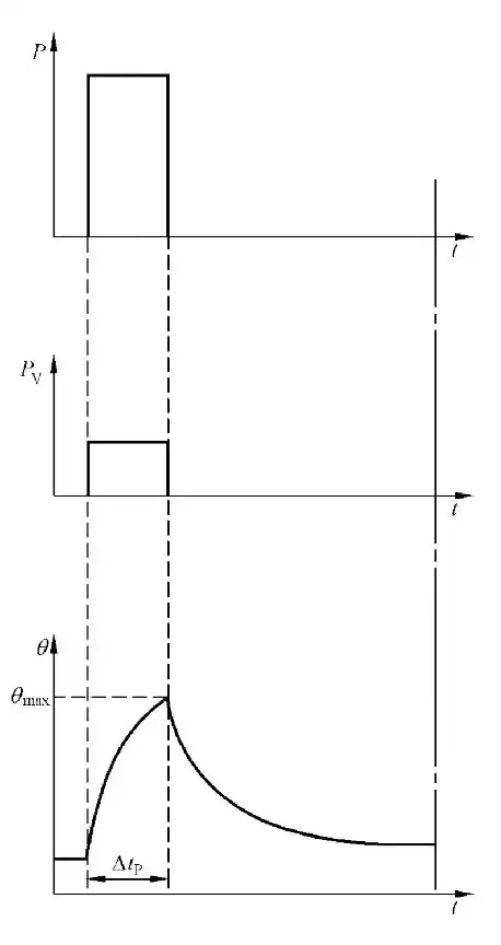
This is the diagram for Short-Time Duty (S2)
This diagram represents the operational characteristics of a motor under the Short-Time Duty (S2) cycle. In this duty type, the motor operates at a constant load for a predefined short period before stopping completely to cool down. Let’s break down the components and symbols represented in the figure:

P (Load)
The P curve in the top graph shows the load applied to the motor. The motor runs at a constant load (Pi) for a specific time, as indicated by the horizontal segment of the curve.

PV (Electrical Loss)
Below the load curve, PV represents the electrical losses during operation. This value remains steady during the load phase, corresponding to the constant load applied to the motor.

θ (Temperature)
The θ curve in the bottom graph indicates the motor’s temperature during operation. Initially, the temperature rises due to the load applied.

θmax (Maximum Temperature)
This represents the maximum temperature reached during the load period (ΔtP). After the load period ends, the motor stops, and the temperature begins to decrease as the motor cools down.

t (Time)
The horizontal axis in all graphs represents time (t).

ΔtP
This is the time during which the motor operates under a constant load. Once ΔtP ends, the motor is turned off, entering a cooling phase with no load applied.
The Short-Time Duty (S2) cycle involves two key phases: Operation Phase: The motor starts and runs at a constant load (Pi) for a short, predefined period (ΔtP).
During this time, the temperature rises steadily, reaching a peak at θmax. Cooling Phase: After the operation phase, the motor shuts down, and no load is applied. During this phase, the temperature decreases as the motor dissipates heat and returns to ambient temperature.
This duty cycle is ideal for applications like cranes, hoists, or electric drills, where short bursts of operation are sufficient, followed by rest periods to prevent overheating. The key advantage of S2 is its ability to handle high loads briefly without exceeding its thermal limits, provided it is allowed adequate cooling time between cycles.
Video Resources: How to Calculate Motor Temperature Under Load

2.3 Intermittent Periodic Duty (S3)
2.3.1 Definition and Characteristics:
Intermittent periodic duty (S3) involves a sequence of identical operation cycles, each consisting of a period of operation under load followed by a period of no-load running or rest. The motor does not reach thermal equilibrium within a single cycle.
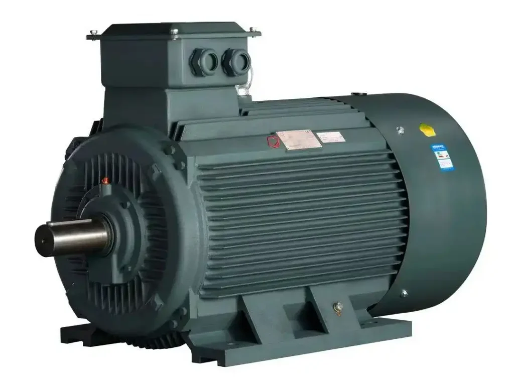
2.3.2 Explanation of the Diagram for Intermittent Periodic Duty (S3)
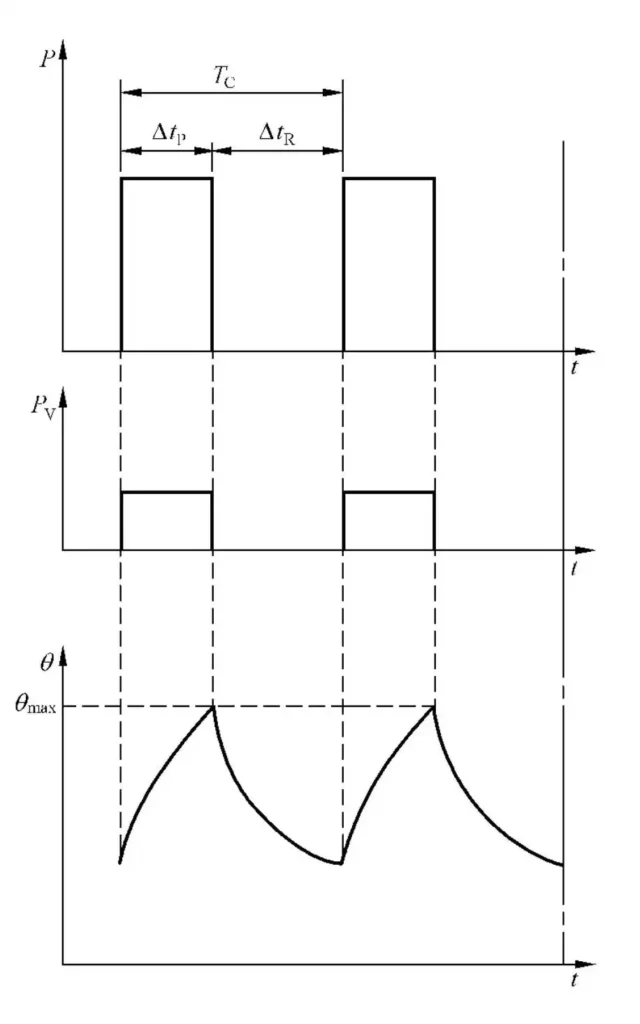
This is the diagram for Intermittent Periodic Duty (S3)
This diagram illustrates the operating characteristics of a motor under Intermittent Periodic Duty (S3). In this duty type, the motor alternates between a period of operation under constant load and a period of rest or no-load running, with no thermal equilibrium reached during a single cycle. Below is an explanation of the symbols and their relevance to the curves in the diagram:

P (Load)
1.The P curve in the top graph represents the load applied to the motor. 2.The motor operates under a constant load (Pi) for a defined time during each cycle, followed by a no-load period.

PV (Electrical Loss)
PV, the electrical loss, corresponds to the motor's power consumption during operation. It appears as constant horizontal lines during the load period and drops to zero during the no-load rest phase.

θ (Temperature)
1.The θ curve in the bottom graph shows the motor’s temperature over time. 2.During the load phase, the temperature rises but does not reach the maximum permissible 3.During the rest phase, the temperature decreases as the motor cools down before the next cycle begins.

TC (Load Cycle Duration)
1.TC represents the total cycle time, including both the load period (ΔtP) and the rest period (ΔtR). 2.ΔtP: The time during which the motor operates under a constant load. 3.ΔtR: The time allocated for rest or no-load running, allowing the motor to partially cool down.

θmax (Maximum Temperature)
The highest temperature achieved during the load phase of each cycle. The motor’s temperature remains below θmax due to the cooling effect during the rest phase.
The Intermittent Periodic Duty (S3) cycle is a repetitive sequence of:
- Load Phase (ΔtP):The motor runs under a constant load (Pi) for a defined time. During this period, the temperature gradually rises.
- Rest Phase (ΔtR):The motor rests or operates without load, allowing its temperature to decrease.
This duty cycle ensures that the motor avoids overheating by incorporating sufficient rest periods between operational phases. It is ideal for applications like welding machines, elevators, and material handling systems, where predictable work and rest cycles are required. The balance between load and rest ensures efficiency while maintaining thermal limits.

2.4 Intermittent Periodic Duty with Starting (S4)
2.4.1 Definition and Characteristics:
Intermittent periodic duty with starting (S4) adds a significant load during the starting phase to the intermittent periodic operation cycle. Each cycle consists of a starting period, a load period, and a rest or idle period.
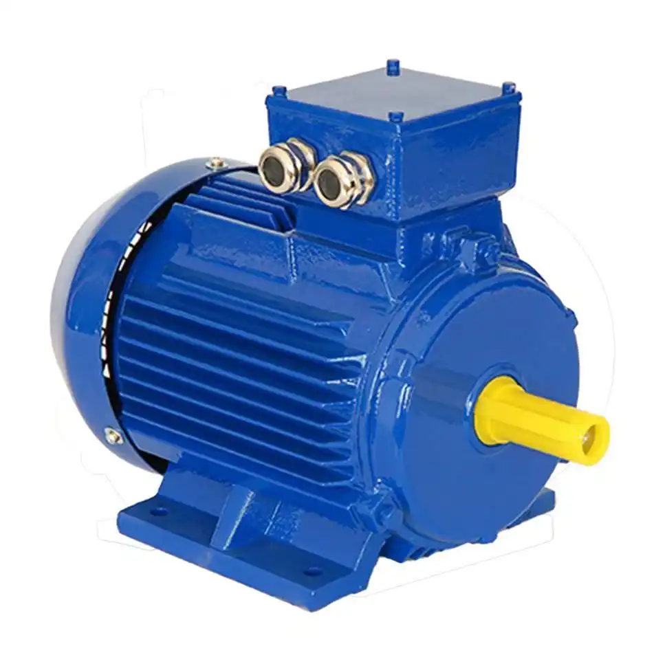
2.4.2 Explanation of the Diagram for Intermittent Periodic Duty with Starting (S4)
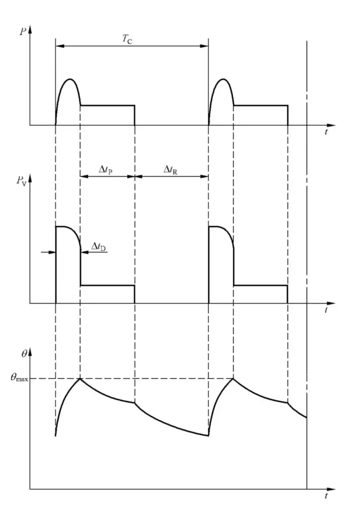
This is the diagram for Intermittent Periodic Duty (S4)
This diagram illustrates the characteristics of Intermittent Periodic Duty with Starting (S4). In this duty type, each cycle includes a starting phase, a constant load operation phase, and a resting phase, with no thermal equilibrium reached during a single cycle. Here’s a breakdown of the symbols and their relationships as shown in the diagram:

P (Load)
1.The P curve at the top represents the motor's load over time. 2.During each cycle, the motor undergoes a sharp increase in load at the start (ΔtD) and then operates at a constant load (ΔtP).

θ (Temperature)
- The θ curve at the bottom indicates the motor’s temperature over time.
- During the starting phase (ΔtD), temperature rises sharply due to the high energy demand.
- In the constant load phase (ΔtP), temperature continues to rise but at a slower rate.
- During the resting phase (ΔtR), the motor cools down as no load is applied, but it does not return to ambient temperature, leading to cumulative heating over successive cycles.
- θmax: Represents the maximum temperature the motor reaches during a cycle.

TC (Load Cycle Duration)
TC represents the total duration of one load cycle, including the starting phase (ΔtD), constant load operation phase (ΔtP), and resting phase (ΔtR).
The Intermittent Periodic Duty with Starting (S4) cycle includes three key phases:
- Starting Phase (ΔtD):The motor begins operation, overcoming inertia with high torque and power demand. This phase generates significant heat.
- Constant Load Phase (ΔtP):After starting, the motor operates at a steady load, during which temperature rises further but more gradually.
- Resting Phase (ΔtR):The motor stops and cools down during the rest period. However, the temperature does not return to ambient levels, resulting in cumulative heating over successive cycles.
This duty type is commonly used in applications like elevators, conveyor systems, and hoists, where frequent starting and stopping are required. Proper thermal management and motor selection are critical to ensure reliable operation and prevent overheating in S4 duty applications.

2.5 Intermittent Periodic Duty with Electric Braking (S5)
2.5.1 Definition and Characteristics:
Intermittent periodic duty with electric braking (S5) is a cycle where the motor undergoes frequent starting, load operation, and stopping, with braking achieved using an electric braking system. Each cycle includes a braking phase, adding thermal stress to the motor.
2.5.2 Explanation of the Diagram for Intermittent Periodic Duty with Electric Braking (S5)
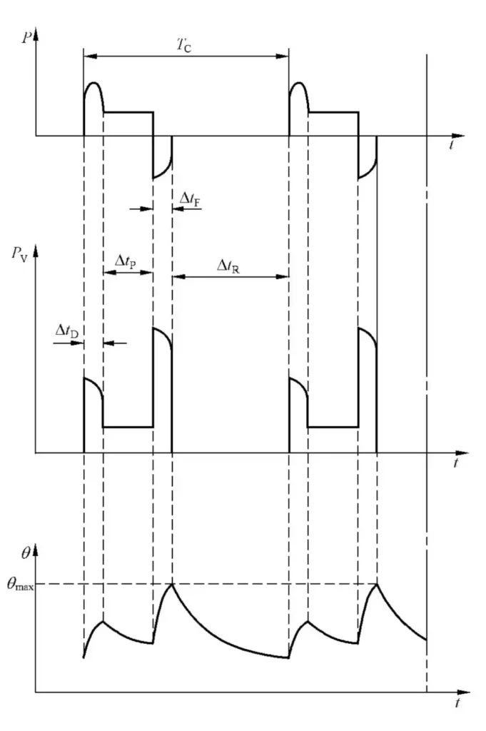
This is the diagram for Intermittent Periodic Duty with Electric Braking (S5)
The diagram represents the characteristics of a motor operating under Intermittent Periodic Duty with Electric Braking (S5). In this duty type, each cycle consists of a starting phase, a period of operation under constant load, a braking phase, and a resting phase. Below is an explanation of the symbols relevant to this curve:

P (Load)
1.The P curve at the top shows the load applied to the motor during the cycle. 2.The load increases sharply during the starting phase (ΔtD), remains constant during the operational phase (ΔtP), and then drops during the braking phase (ΔtF).

θ (Temperature)
- The θ curve at the bottom graph indicates the motor's temperature over time.
- During the starting phase (ΔtD) and braking phase (ΔtF), the motor's temperature increases due to the energy required for acceleration and braking.
- During constant load operation (ΔtP), the temperature continues to rise but at a slower rate.

TC (Load Cycle Duration)
TC represents the total time for one cycle, including starting (ΔtD), constant load operation (ΔtP), braking (ΔtF), and resting (ΔtR) phases.

PV (Electrical Loss)
1.PV, shown in the middle graph, represents the electrical losses during operation. 2.Losses are highest during the starting phase (ΔtD) and the braking phase (ΔtF). During constant load operation (ΔtP), losses stabilize at a lower, steady level. In the resting phase (ΔtR), losses drop to zero.
In Intermittent Periodic Duty with Electric Braking (S5), each cycle follows this sequence:
- Starting Phase (ΔtD):The motor begins operation, requiring high torque and energy, causing a sharp temperature rise.
- Constant Load Phase (ΔtP):The motor operates at a steady load, with a gradual increase in temperature.
- Braking Phase (ΔtF):Electric braking is applied to stop the motor, generating additional heat and increasing electrical losses.
- Resting Phase (ΔtR):The motor cools down during this period of inactivity, but the temperature does not fully return to ambient levels, resulting in cumulative heating over multiple cycles.
This duty type is commonly used in applications requiring frequent starts, stops, and braking, such as cranes, hoists, and industrial machinery. Proper thermal and mechanical management ensures the motor operates reliably under these demanding conditions.

2.6 Continuous Duty with Intermittent Periodic Load Variations (S6)
2.6.1 Definition and Characteristics:
Continuous duty with intermittent periodic load variations (S6) involves the motor operating continuously, but with varying load levels during the cycle. There are no rest or idle periods. Instead, the load alternates between high and low intensities.
2.6.2 Explanation of the Diagram for Continuous Duty with Intermittent Periodic Load Variations (S6)
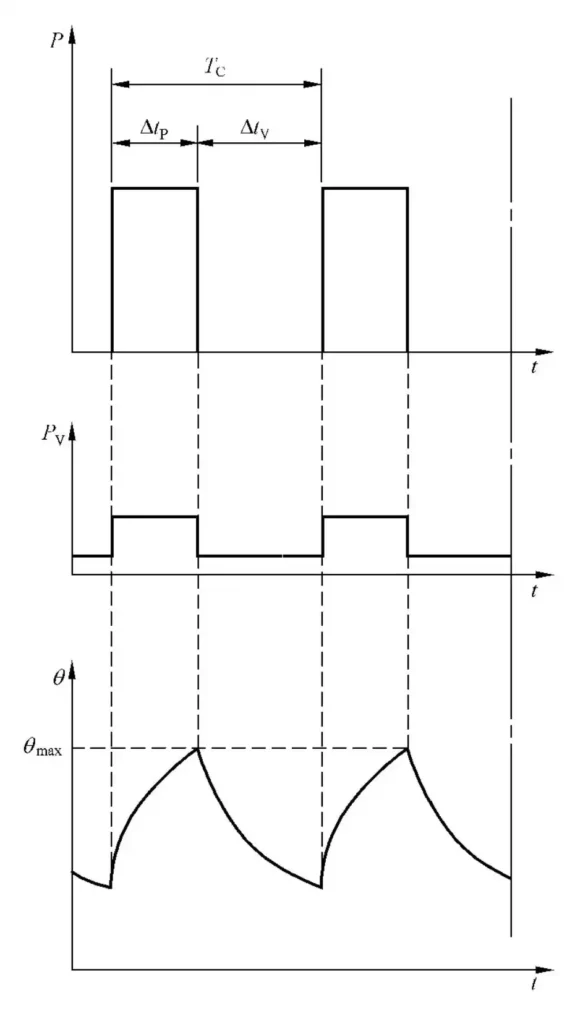
This is the diagram for Intermittent Periodic Load Variations (S6)
This diagram illustrates the operational characteristics of a motor working under Continuous Duty with Intermittent Periodic Load Variations (S6). In this duty type, the motor alternates between running under load and running without load (idle), but it operates continuously without stopping. Here’s a detailed explanation of the relevant symbols and their representation in the diagram:

P (Load)
- The P curve at the top shows the motor's load over time.
- During the load phase (ΔtP), the motor operates under a constant load (Pi).
- During the no-load phase (ΔtV), the motor runs without a load, but it remains operational.

PV (Electrical Loss)
- PV represents the electrical losses during operation.
- Losses are steady during the load phase (ΔtP) and reduce to a lower level during the no-load phase (ΔtV).
- Unlike other duty types with complete rest phases, losses never drop to zero in S6 because the motor continues to run during no-load periods.

θ (Temperature)
- The θ curve at the bottom graph illustrates the motor's temperature behavior over time.
- During the load phase (ΔtP), the temperature rises as the motor generates heat.
- During the no-load phase (ΔtV), the temperature decreases slightly due to reduced power losses, but it does not cool significantly as the motor remains active.
- θmax: Represents the maximum temperature reached during the load phase, which remains below the thermal limit.

TC (Load Cycle Duration)
TC represents the total duration of one cycle, including both the load phase (ΔtP) and the no-load phase (ΔtV).
In Continuous Duty with Intermittent Periodic Load Variations (S6), the motor operates continuously without any rest periods, alternating between:
- Load Phase (ΔtP):The motor carries a constant load (Pi) during this phase, resulting in steady electrical losses and a gradual increase in temperature.
- No-Load Phase (ΔtV):The motor runs without load, reducing electrical losses and causing the temperature to drop slightly.
This duty type is suitable for applications like fans or pumps with fluctuating demands, where the motor operates continuously but alternates between loaded and idle periods. The key advantage of S6 is its ability to handle intermittent load variations without stopping, ensuring seamless operation while managing thermal limits effectively.

2.7 Continuous Duty with Electric Braking (S7)
2.7.1 Definition and Characteristics:
Continuous duty with electric braking (S7) involves the motor running continuously under load while incorporating frequent braking phases using electric braking systems. This duty cycle is characterized by the absence of rest or idle periods.
2.7.2 Explanation of the Diagram for Continuous Duty with Electric Braking (S7)
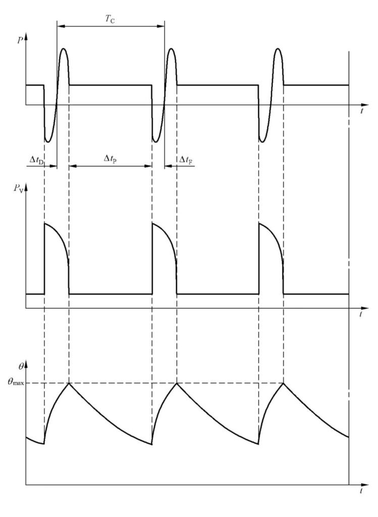
This is the diagram for Continuous Duty with Electric Braking (S7)
This diagram illustrates the operational behavior of a motor under Continuous Duty with Electric Braking (S7). In this duty type, the motor operates continuously but alternates between starting, constant load, and electric braking phases within each cycle. Below is the explanation of the relevant symbols based on the curves shown:

P (Load)
- The P curve represents the load applied to the motor.
- Each cycle starts with a sharp load increase during the starting phase (ΔtD), transitions into a constant load operation phase (ΔtP), and then enters the braking phase (ΔtF), where the load decreases rapidly as the motor decelerates.

PV (Electrical Loss)
- PV, the electrical loss curve, shows the power consumption at various phases of the cycle.
- Losses are highest during the starting phase (ΔtD) and the braking phase (ΔtF) due to high energy requirements.
- During the constant load operation phase (ΔtP), the losses stabilize at a steady level, reflecting efficient operation.

θ (Temperature)
- The θ curve represents the motor's temperature over time.
- Temperature rises sharply during the starting phase (ΔtD) due to high power demand.
- During the constant load phase (ΔtP), the temperature continues to increase gradually as heat accumulates.
- During the braking phase (ΔtF), the motor generates additional heat due to energy dissipation, causing a small temperature spike.
- Overall, the temperature fluctuates across cycles, but it stabilizes below the maximum allowable level (θmax) over time.

TC (Load Cycle Duration)
TC is the total duration of one cycle, including starting (ΔtD), constant load operation (ΔtP), and braking (ΔtF).
In Continuous Duty with Electric Braking (S7), each cycle consists of three key phases:
- Starting Phase (ΔtD):The motor begins operation, drawing high energy to overcome inertia, causing a sharp temperature rise.
- Constant Load Phase (ΔtP):The motor operates at a steady load, with stable electrical losses and a gradual increase in temperature.
- Braking Phase (ΔtF):The motor decelerates using electric braking, generating additional heat and causing a temperature spike.
This duty type is ideal for applications requiring precision, such as robotics or material handling systems, where frequent starts, stops, and controlled braking are necessary. Proper thermal management ensures the motor operates reliably and stays within its thermal limits despite the repetitive braking phases.

2.8 Continuous Duty with Load Variations (S8)
2.8.1 Definition and Characteristics:
Continuous duty with load variations (S8) involves the motor operating continuously but under varying loads and speeds during the cycle. This duty cycle accommodates shifts in operational demands without interrupting the motor’s runtime.
2.8.2 Explanation of the Diagram for Continuous Duty with Load Variations (S8)
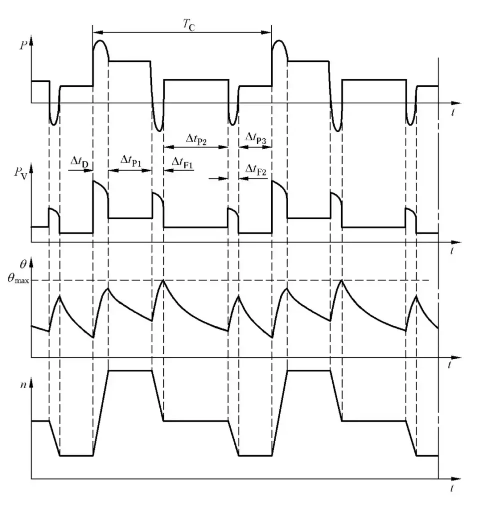
This is the diagram for Continuous Duty with Load Variations (S8)
This diagram illustrates the operational characteristics of a motor under Continuous Duty with Load Variations (S8). In this duty type, the motor operates continuously, but the load varies during each cycle, resulting in temperature and power changes. Below is an explanation of the relevant symbols and their representation in the diagram:

P (Load)
- The P curve represents the motor's load during the operation cycle.
- The load alternates between different levels during the cycle, as shown by multiple distinct load segments (ΔtP1, ΔtP2, and ΔtP3).
- These variations demonstrate that the motor is operating under fluctuating load conditions.

PV (Electrical Loss)
- PV shows the electrical losses corresponding to the load.
- Electrical losses vary proportionally with the load during each phase (ΔtP1, ΔtP2, and ΔtP3) and are higher during phases of increased load.
- There are no complete rest periods, as the motor operates continuously.

θ (Temperature)
- The θ curve depicts the temperature fluctuations caused by load variations.
- During higher load phases, the temperature rises more steeply, approaching θmax.
- In lower load phases, the rate of temperature increase slows, allowing partial cooling, but the motor temperature does not drop significantly.

n (Speed)
- The n curve represents the motor's rotational speed.
- Speed also fluctuates according to load variations, aligning with each load segment (ΔtP1, ΔtP2, and ΔtP3).

TC (Load Cycle Duration)
TC represents the total duration of one cycle, encompassing all the load phases (ΔtP1, ΔtP2, and ΔtP3).
In Continuous Duty with Load Variations (S8), the motor operates continuously while alternating between different load levels. The operation follows this sequence:
- Load Variation Phases (ΔtP1, ΔtP2, ΔtP3):The motor handles varying loads during these phases, causing fluctuations in electrical losses, temperature, and speed.
- Temperature Dynamics:The motor’s temperature increases during higher load phases and stabilizes or cools slightly during lower load phases.
This duty type is ideal for applications like industrial machinery and processing equipment, where load requirements change continuously over time. Proper thermal and mechanical management ensures the motor can handle these variations without exceeding its operational limits.

2.9 Duty with Non-Periodic Load and Speed Variations (S9)
2.9.1 Definition and Characteristics:
Duty with non-periodic load and speed variations (S9) involves the motor operating under conditions where load and speed fluctuate unpredictably. These changes are not cyclic, and the motor experiences a wide range of torque and speed demands during operation.
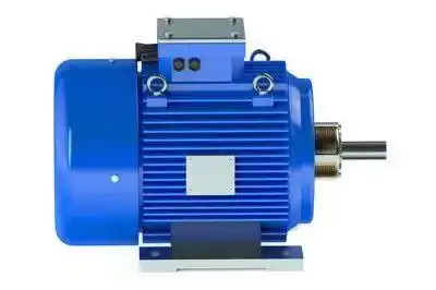
2.9.2 Explanation of the Diagram for Duty with Non-Periodic Load and Speed Variations (S9)
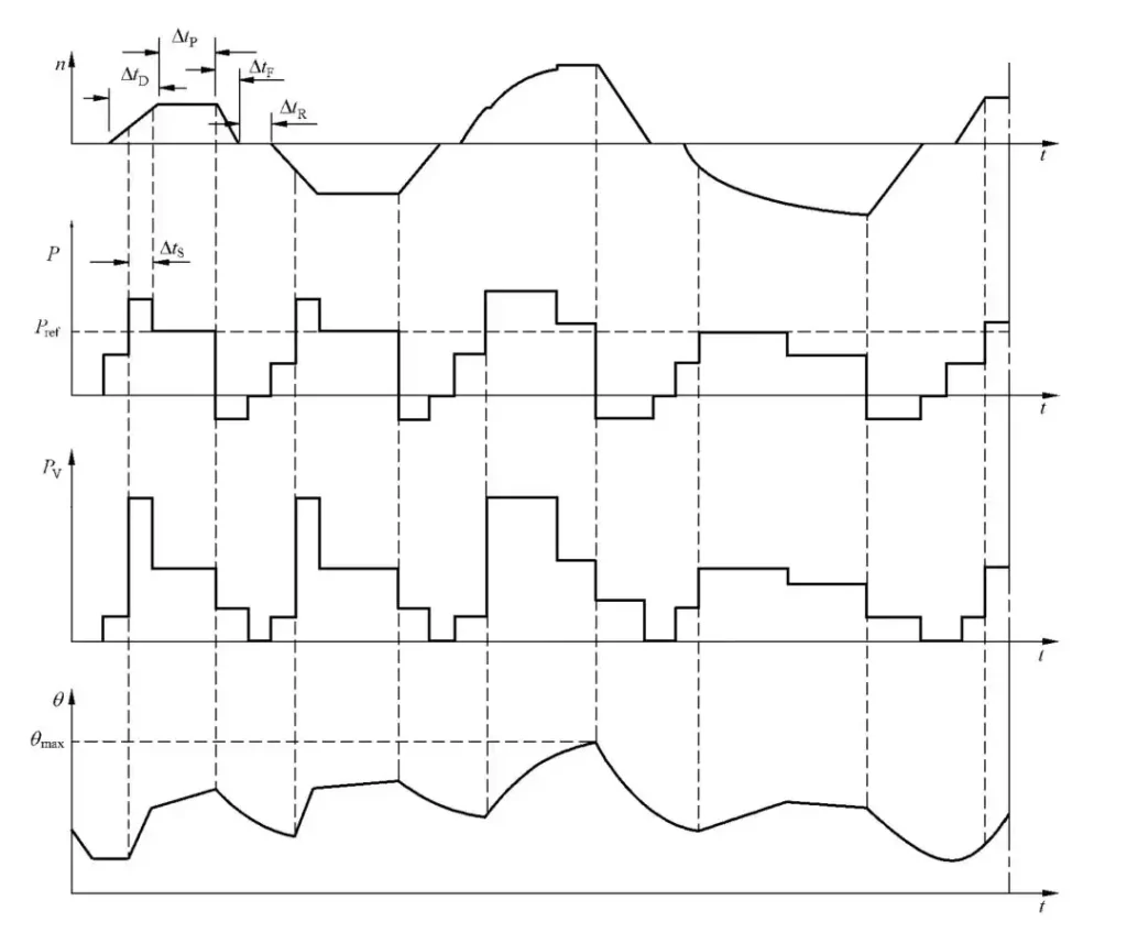
This is the diagram for Non-Periodic Load and Speed Variations (S9)
This diagram illustrates the behavior of a motor operating under Duty with Non-Periodic Load and Speed Variations (S9). In this duty type, the motor is subjected to highly variable loads and speeds without a repetitive or predictable pattern. Below is an explanation of the relevant symbols and their interpretation in the context of the diagram:

n (Speed)
- The n curve represents the rotational speed of the motor.
- It fluctuates irregularly, reflecting the non-periodic nature of the duty cycle. The motor speed increases and decreases as dictated by varying operational demands.

P (Load)
- The P curve represents the load applied to the motor, which varies unpredictably.
- At times, the motor operates at higher loads (ΔtS) and at other moments at lower or moderate loads.

PV (Electrical Loss)
- PV, the electrical loss curve, varies in direct proportion to the load.
- During higher load phases, electrical losses are higher. During lower load periods, the losses decrease accordingly.

θ (Temperature)
- The θ curve depicts the temperature of the motor over time.
- Temperature fluctuates along with the load and speed, rising sharply during high-load intervals and stabilizing or cooling slightly during lighter load phases.
- Despite the irregular variations, the temperature remains below the maximum permissible limit (θmax).

TC (Load Cycle Duration)
TC represents the total cycle time. However, unlike other duty types, TC in S9 does not follow a fixed pattern due to the non-periodic nature of load and speed variations.
In Duty with Non-Periodic Load and Speed Variations (S9), the motor operates under constantly changing conditions without a regular or predictable pattern. The operation is characterized by:
- Variable Speed and Load:The motor adjusts its speed and load in response to dynamic operational requirements.
- Fluctuating Electrical Losses and Temperature:Electrical losses and temperature increase during high-load phases and decrease during lighter load periods.
- Non-Repeating Patterns:Unlike periodic duty types, the motor operates in an irregular and non-repeating manner.
This duty type is ideal for applications such as robotics, cranes, or complex industrial machinery, where operational demands are unpredictable and continuously changing. Proper monitoring and thermal management are essential to ensure reliable performance under such dynamic conditions.

2.10 Duty with Discrete Constant Load Speeds (S10)
2.10.1 Definition and Characteristics:
Duty with discrete constant load speeds (S10) consists of a series of defined operating conditions, each with a constant load and speed. The motor alternates between these conditions based on predefined settings or operational needs.
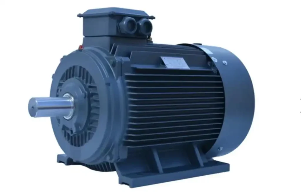
2.10.2 Explanation of the Diagram for Duty with Discrete Constant Load Speeds (S10)
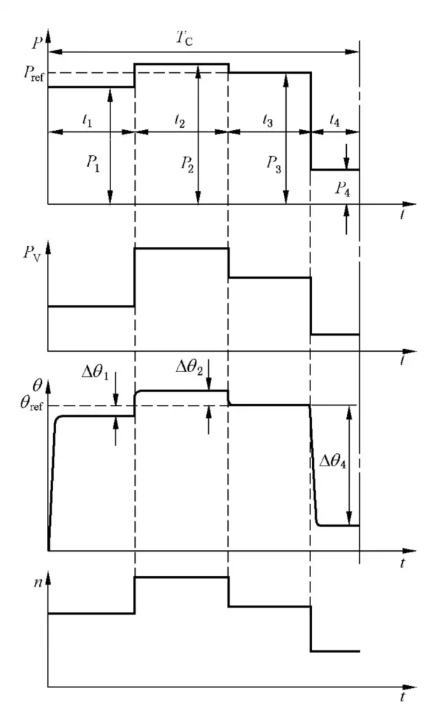
This is the diagram for Discrete Constant Load Speeds (S10)
This diagram represents the behavior of a motor under Duty with Discrete Constant Load Speeds (S10). In this duty type, the motor operates continuously but alternates between distinct constant load speeds within each cycle. Below is an explanation of the relevant symbols and their interpretation based on the diagram:

P (Load)
- The P curve at the top indicates the load applied to the motor.
- The losses increase or decrease in accordance with the transitions between the load levels.
- For instance, electrical losses are higher during phases with greater loads (P3 and P4) and lower during lighter load phases (P1 and P2).

θ (Temperature)
- The θ curve illustrates the motor's temperature over time.
- Each discrete load phase corresponds to a specific temperature increase (Δθ1, Δθ2, Δθ3, Δθ4), depending on the load's magnitude.
- During higher load phases, temperature rises more sharply, while in lighter load phases, it either stabilizes or cools slightly.

n (Speed)
- The n curve at the bottom graph shows the motor's speed, which varies discretely to match the load levels (P1, P2, P3, P4).
- Each distinct load phase corresponds to a constant speed setting.

TC (Load Cycle Duration)
TC is the total duration of one cycle, including all discrete load levels and transitions.
In Duty with Discrete Constant Load Speeds (S10), the motor follows a continuous cycle alternating between different constant load levels. The operation sequence is as follows:
- Discrete Load Phases:The motor transitions between multiple distinct load levels (P1, P2, P3, P4), with each load phase associated with a constant speed.
- Temperature Dynamics:The temperature adjusts dynamically, increasing during heavier load phases and stabilizing or cooling during lighter load phases.
- Efficiency Management:Electrical losses correlate directly with load levels, with higher losses during heavier load phases.
This duty type is commonly used in industrial automation and robotics, where the motor needs to operate at multiple predefined speed and load settings. Proper thermal and electrical loss management ensures reliable operation across the varying load conditions.
Video Resources: Study S1-S10 Duty cycle of the electric motors.

3. FAQs
1. What is the most common motor duty cycle?
The most common motor duty cycle is Continuous Duty (S1).
2. How do I determine the duty cycle of my motor?
- Check the Nameplate or Documentation:Manufacturers often label the motor’s duty cycle (e.g., S1, S2) on the nameplate or in the technical specifications.
- Analyze the Application Requirements:Identify the load patterns, runtime duration, and cooling intervals in your operation.
- Match the Cycle to the Workload:Compare your application needs to the standard duty cycles defined by IEC to find the most suitable one.
3. What are the consequences of using the wrong duty cycle?
- Overheating:Motors not rated for continuous operation may overheat under constant use.
- Inefficiency:Motors designed for intermittent operation waste energy if left idle for extended periods.
- Shortened Lifespan:Overloading or misusing a motor accelerates wear and tear.
- Operational Failures:Incorrect duty cycles can result in motor breakdowns, causing costly downtime.
4. How do duty cycles impact energy efficiency?
Duty cycles optimize energy use by aligning motor operation with specific application needs:
- Continuous Duty (S1):Maintains steady performance, ideal for consistent loads.
- Intermittent Duty (S3):Balances work and rest, reducing energy consumption during idle periods.
- Non-Periodic Variations (S9):Adjusts dynamically to changing loads, preventing energy waste.
Choosing the correct duty cycle ensures efficient power usage, minimizes heat loss, and reduces operational costs. This alignment is key to achieving both optimal performance and sustainability.


