3-Phase AC Induction Motor | Working Principle, Definition & Types
27/11/2024

Sam Nie
Hello every one. This is Sam Nie, the CEO of LUPMOTORS. With 10 year's technical and manufacture experience in the field of 3-phase electric motor, I can provide you definitive guides in the knowledge of 3-phase industrial electric motors,which will help you a lot in selecting electric motors for your applications.
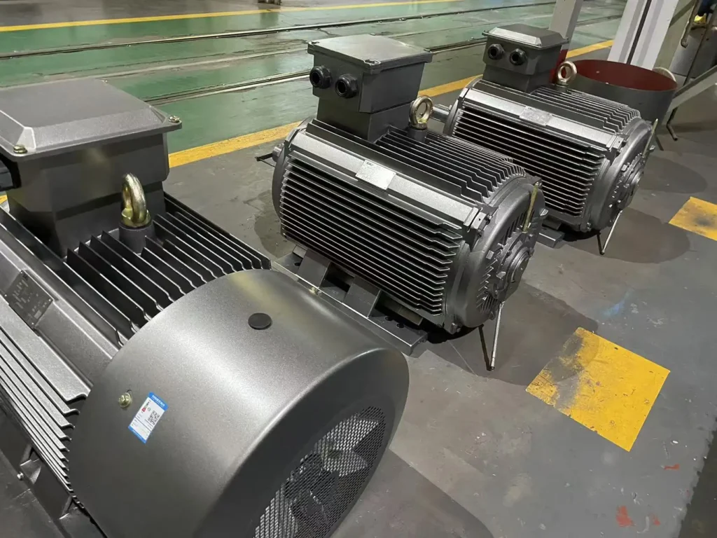
Have you ever wondered what keeps factories humming, conveyor belts moving, and industrial machines roaring? That’s where the 3-phase AC induction motor steps in. It’s an unsung hero of modern industry—efficient, reliable, and built to handle tough jobs. These motors are found everywhere, from manufacturing plants to HVAC systems, powering the backbone of industries worldwide.
In this article, we’ll talk about what a 3-phase AC induction motor is, how it works, its structure, and the different types available. We’ll also dive into its applications, advantages, and even some recent innovations. Ready to dig in? Let’s get started!
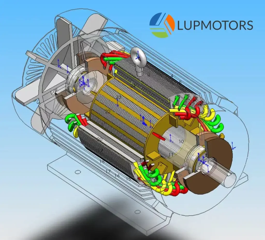
Table of Contents
1.What is a 3-Phase AC Induction Motor?
1.1 The Basic Knowledge About The 3-Phase Motor

Electricity
Mechanical Energy
A 3-phase AC induction motor is a type of electric motor that converts electrical energy into mechanical energy using three-phase alternating current (AC).
3-phase induction AC motors are widely known for being simple, durable, and reliable, so they are widely uesd for industrial applications.

Simple

Durable

Reliable
Unlike single-phase motors, 3-phase induction motors are self-starting, thanks to the rotating magnetic field created by the three-phase power supply.

1.2 Faraday’s Law of Electromagnetic Induction
Faraday’s Law is the science behind the magic. It explains how electrical energy gets transformed into mechanical motion. Simply put, when a conductor (like the rotor in our motor) moves through a magnetic field, it induces an electric current. This current then interacts with the magnetic field to produce motion.
Here’s the gist of Faraday’s Law in action:

1.A changing magnetic field creates an electric current.
2.The induced current opposes the change that caused it (Lenz’s Law).

3.The magnitude of the induced current depends on the rate of change of the magnetic field.
The right-hand rule
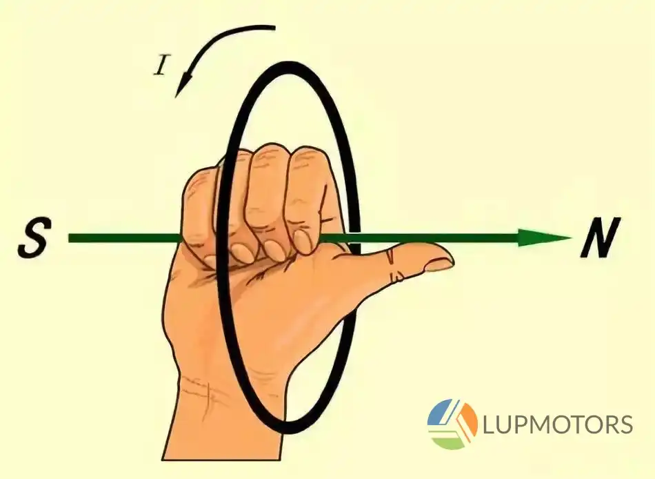
Photo: It illustrates the right-hand rule.
One helpful tool to understand the direction of the induced current is the right-hand rule. Simply put, your thumb points in the direction of the motion of the conductor, your index finger aligns with the magnetic field, and your middle finger shows the direction of the induced current.
This rule makes it easy to visualize how the interaction of magnetic fields and currents creates motion in the rotor.
Video Resources
By combining Faraday’s Law and the right-hand rule, we can better grasp the elegant physics powering these motors.
1.3 What is 3-Phase Power?
Three phase power is the lifeblood of this motor. It’s a type of electrical supply where three currents flow at the same frequency but are offset by 120 degrees. This offset creates a smooth, continuous flow of power, perfect for driving motors efficiently. 3-phase power delivers 1.73 times the power of single-phase power for the same current level.
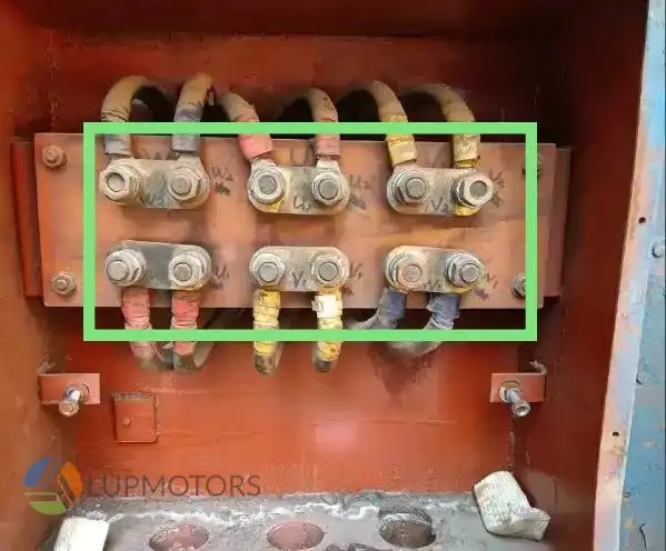
Photo:This is the Terminal Box of a 3-phase ac induction electric motor. You can see there are 6 connectors for 3 phase.
Example: A 10 kW load requires 45 amps on a single-phase system but only 26 amps on a 3-phase system, reducing the strain on wiring and equipment.
Why is 3-phase power so special?

It provides constant torque, avoiding the jerky motion seen in single-phase systems.

It’s more energy-efficient, ideal for industrial machines.

It reduces power loss over long distances, making it cost-effective.
Now that you know the basics, let’s explore what makes these motors tick—their structure and design.

2.Structure of a 3-Phase AC Induction Motor
A 3-phase AC induction motor is like a mechanical orchestra, with each component playing its part in perfect harmony. Its design is simple yet sophisticated, built to handle heavy-duty operations with ease. Let’s take a closer look at its two main components: the stator and the rotor.
2.1 The Stator: The Stationary Backbone
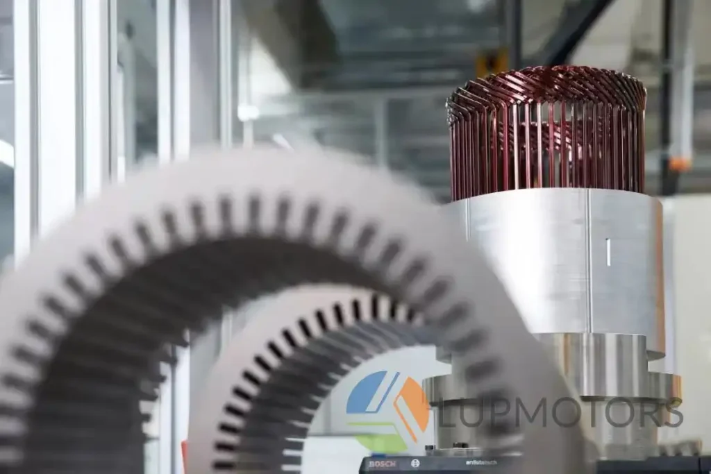
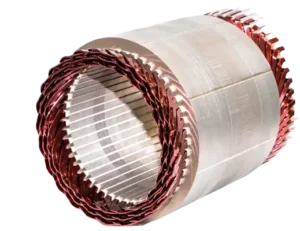
Photo: These are the motor stators.
The stator is the fixed part of a 3-phase AC induction motor. It creates the magnetic field that powers the rotor and ultimately drives the motor’s operation. Let’s dive into its critical components and their roles.
Let’s study the key components of the stator together.
1.Stator Frame

2.Stator Core
3.Stator Winding

2.1.1 Stator Frame
The Stator frame is the sturdy outer casing that holds the stator in place and protects its internal components.

Common materials
Click it for more contents
Cast iron for heavy-duty industrial applications or aluminum for lightweight motors.

Heat Dissipation
Click it for more contents
Industrial-grade motors often have stator frames with cooling fins to dissipate heat more effectively.

Standard
Click it for more contents
There are different frame standards for the stator frame. Different standards make different frame sizes. The common standards are IEC and NEMA Standards.
Comparison : NEMA vs. IEC Metrics

2.1.2 Stator Core
The stator core is a critical component in a 3-phase AC induction motor, acting as the pathway for the magnetic field created by the stator windings.
-

1.Built from laminated steel sheets (each 0.35–0.50 mm thick) stacked together.
-

2.Why laminations? They reduce energy losses caused by eddy currents, improving the motor’s efficiency.
-

3.Data Point: Using laminated cores can cut eddy current losses by 40–60% compared to solid cores.
-

4.There are many slots on the stator core in order to put another important part of the electric motor---Stator Winding.

2.1.3 Stator Winding
Conductive copper or aluminum coils are embedded in the core slots, which are the winding. When energized by a 3-phase AC supply, the windings produce a rotating magnetic field in the stator.

1.Configured in a three-phase arrangement to create a rotating magnetic field.
2.Energy Transfer:The windings are the point where electrical energy from the power supply enters the motor, converting it into magnetic energy for motion.
The stator winding configuration directly impacts the speed of a 3-phase AC induction motor. The number of poles in the stator winding determines the motor’s synchronous speed. The more poles it has, the low speed it is.
Formula:
Speed (RPM) = (120 × Frequency) / Number of Poles
Here is a RPM calculator. You can input the Frequency and Number of poles. The RPM will be displayed.
RPM Calculator
Speed (RPM): -
The stator winding is directly connected to the motor’s terminal box, serving as the interface for power input and configuration adjustments. There are 2 kinds of Connection Types:Star (Y) Connection & Delta (Δ) Connection.
2.2 The Rotor: The Rotating Workhorse
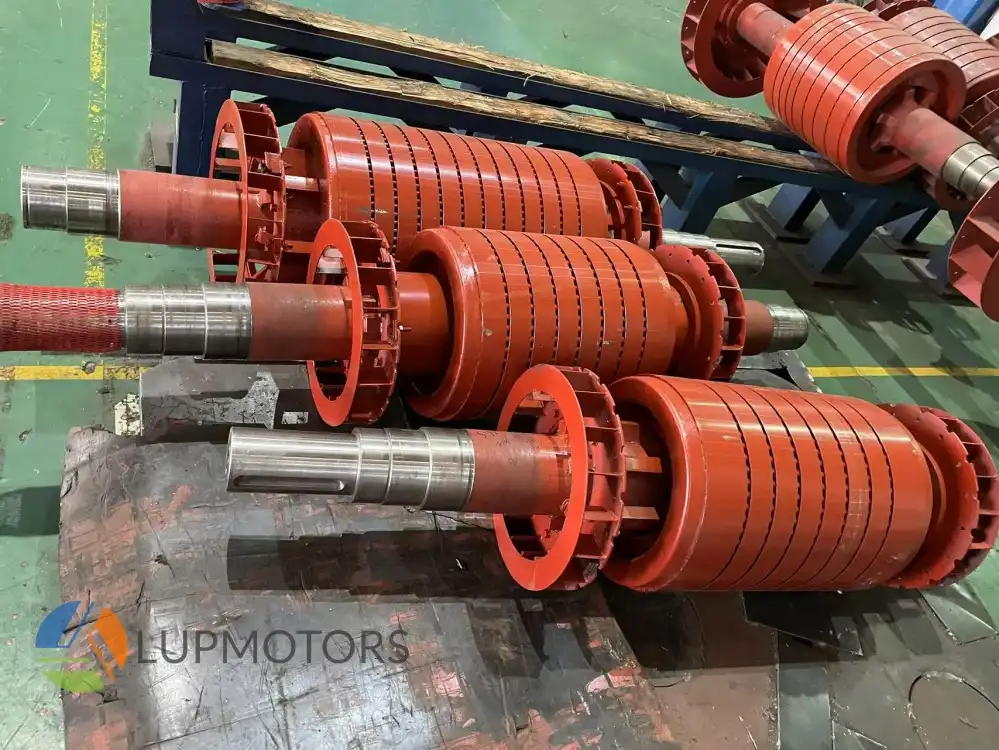
Photo: These are the motor rotor.
The rotor is the heart of the motor, spinning to generate mechanical energy. It’s where the magnetic fields and electrical currents meet to do the heavy lifting.
Let’s study the key components of the Rotor together.

1.Squirrel Cage Rotor

2.Wound Rotor

2.2.1 Squirrel Cage Rotor
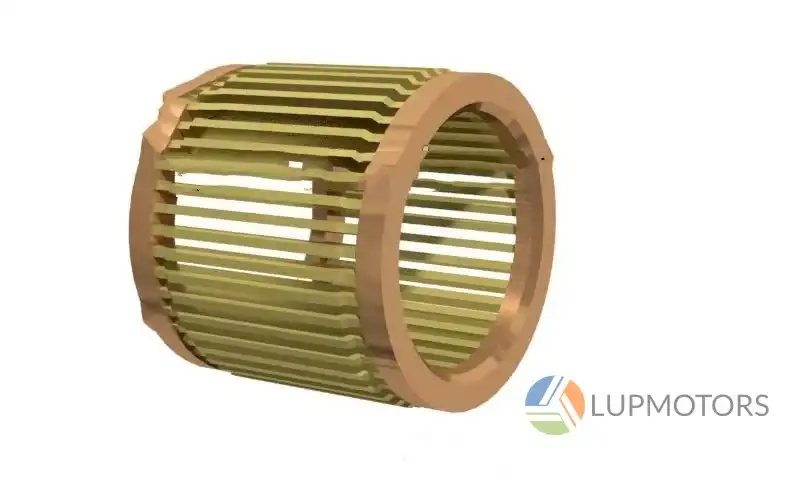
Photo: This is an Squirrel Cage Rotor.
The squirrel cage rotor gets its name from its distinctive shape, resembling a spinning hamster wheel or cage. It consists of a cylindrical core made of laminated steel, with evenly spaced conductive bars running parallel to the shaft. These bars are connected at both ends by thick conductive rings, forming a closed-loop circuit.
This compact, symmetrical design ensures smooth interaction with the stator’s magnetic field, minimizing vibrations and enhancing stability during operation. The shape is simple yet highly efficient, optimized for converting electrical energy into mechanical motion with durability and balance.
Key Functions
-

Materials
Aluminum or copper bars are arranged in a cylindrical pattern, with each end connected by rings. Copper bars can improve motor efficiency by up to 5% compared to aluminum.
-

Efficiency
Data Point: Premium efficiency squirrel cage motors achieve efficiencies above 95% in industrial applications
-

Heat Resistance
High-conductivity materials like copper reduce energy losses and improve thermal stability.
Advantages of Squirrel Cage Rotors
- 1.Simplicity: The design has no external connections, brushes, or slip rings, making it straightforward and easy to manufacture.
- 2.Durability:Rugged construction allows it to withstand harsh environments, high loads, and continuous operation.
- 3.Low Maintenance:The absence of wear-and-tear components, like commutators, minimizes the need for frequent repairs.
- 4.Cost-Effective:Aluminum rotor bars and simple assembly reduce production costs, making these motors affordable for industrial use.
Disadvantages of Squirrel Cage Rotors
- 1.Limited Speed Control:Without additional equipment like Variable Frequency Drives (VFDs), speed adjustment is not possible.
- 2.High Starting Current:At startup, these motors draw a large inrush current, which can stress the power supply without a proper starter.
- 3.Lower Starting Torque:Compared to wound rotor motors, squirrel cage rotors generate lower torque during startup, making them less suitable for high-torque applications like cranes.

2.2.2 Wound Rotor
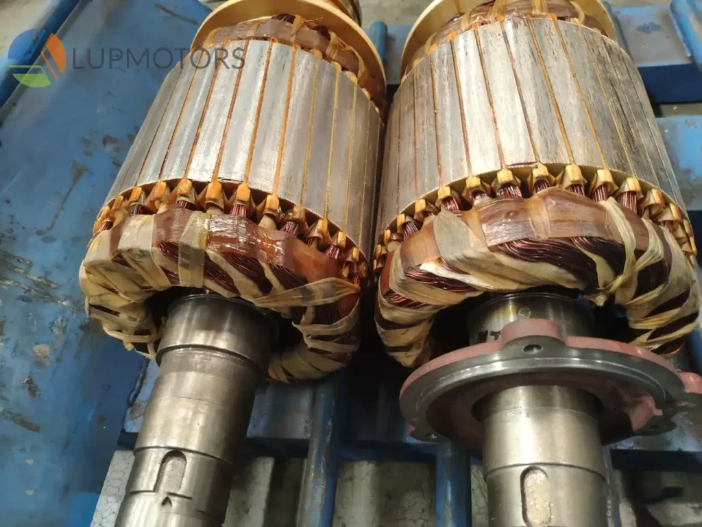
Photo: This is a wound rotor.
The wound rotor features a cylindrical laminated steel core with insulated windings wrapped around its slots, forming distinct phases. Unlike a squirrel cage rotor, it includes slip rings mounted on the shaft, which connect the windings to external circuits via carbon brushes. This design enables precise control of speed and torque by adjusting external resistance.
Its symmetrical shape ensures smooth rotation, while the winding pattern maximizes interaction with the stator’s magnetic field, making it ideal for heavy-duty applications requiring high starting torque and variable speed.
Key Functions
-

Torque Generation
When the rotating magnetic field from the stator cuts through the rotor windings, it induces a current. This current interacts with the magnetic field, creating the torque that drives the motor.
-

Speed and Torque Control
By adjusting the external resistance connected via the slip rings, the rotor’s current can be controlled. This makes wound rotors ideal for applications requiring variable speed or high starting torque, such as cranes and heavy machinery.
-

Efficient Energy Transfer
The rotor effectively transfers the induced energy into mechanical motion, enabling smooth operation under varying loads.
Advantages of Wound Rotors
- 1.High Starting Torque:1.By adding external resistance to the rotor circuit, the starting current is reduced while increasing the starting torque. This is particularly beneficial for heavy-duty applications like cranes, conveyors, and mills.
- 2.Variable Speed Control:1.The ability to adjust resistance through slip rings allows for precise speed control. This makes wound rotor motors ideal for processes where load conditions vary frequently.
- 3.Energy Efficiency During Startup:1.The adjustable resistance minimizes power surges during startup, reducing strain on the motor and power supply.
- 4.Smooth Acceleration:1.External resistance enables controlled acceleration, preventing mechanical stress on the motor and connected equipment.
- 5.Reduced Current Peaks:1.By limiting inrush current, wound rotors protect electrical circuits from overloading during motor start.
Disadvantages of Wound Rotors
- 1.Higher Initial Cost:1.The inclusion of slip rings, brushes, and external resistance mechanisms increases the manufacturing cost compared to squirrel cage rotors.
- 2.Increased Maintenance:1.Slip rings and carbon brushes are subject to wear and tear, requiring regular inspection and replacement.
- 3.Complexity:1.The additional components and external circuitry make wound rotor motors more complex to operate and maintain.
- 4.Lower Efficiency at Full Load:1.The energy losses in external resistance can lead to slightly lower efficiency during continuous operation compared to squirrel cage motors.
- 5.Space Requirements:1.The external resistor bank and other components occupy additional space, which may be a limitation in compact installations.

3.Working Principle of a 3-Phase AC Induction Motor
A 3-phase AC induction motor works like magic—turning electrical energy into mechanical motion. But behind the scenes, it’s a beautifully orchestrated dance between magnetic fields, currents, and torque. Let’s study it together.
3.1 The Rotating Magnetic Field (RMF)
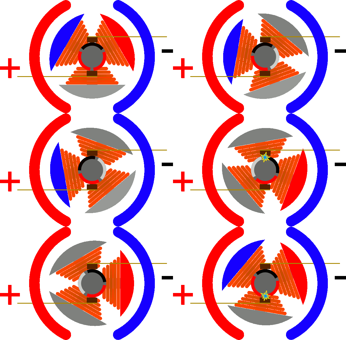
Photo:A rotating magnetic field is occurred when a 3-phase AC supply is connected to the stator
The magic starts in the stator. When a 3-phase AC supply is connected to the stator windings, it produces a rotating magnetic field. This field sweeps across the rotor, creating a dynamic magnetic environment.
Why does this happen? You need to review the Faraday’s Law I have mentioned above.
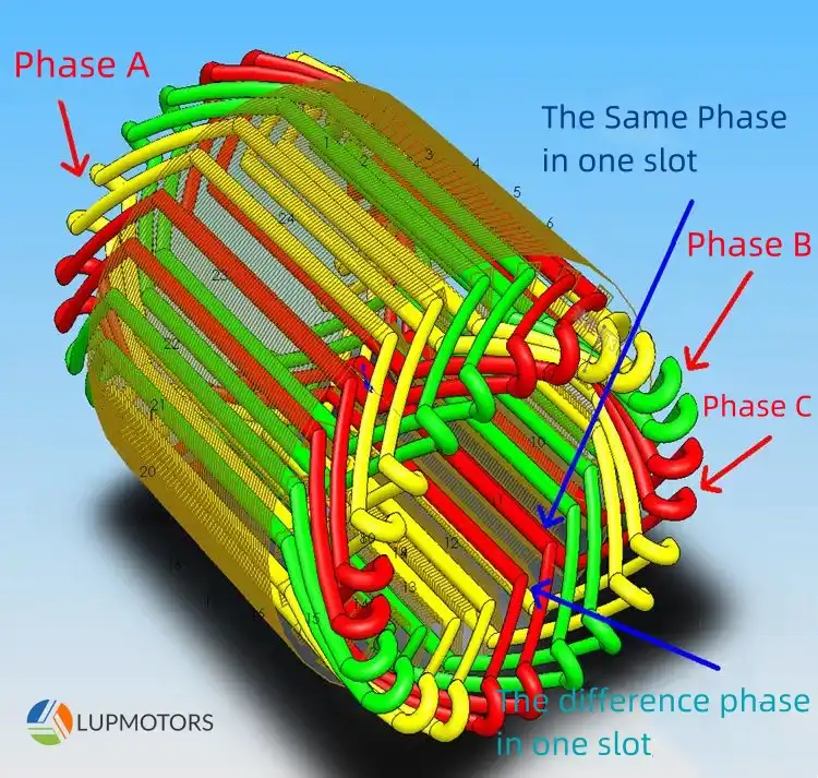
When a 3-phase AC current is applied to the stator windings, it creates a rotating magnetic field.This field alternates and moves because of the nature of the 3-phase supply, where each phase is offset by 120 degrees.This dynamic magnetic field constantly changes position, sweeping across the stationary rotor.
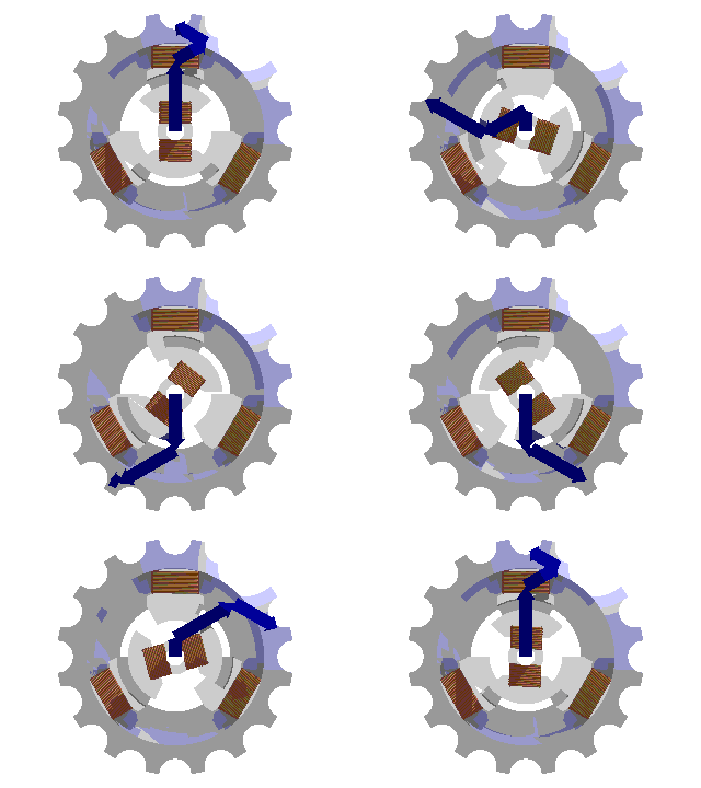
The induced current in the rotor interacts with the magnetic field of the stator. This interaction creates a force, or torque, on the rotor. The torque causes the rotor to start spinning, always lagging slightly behind the stator’s magnetic field. This lag, known as slip, is essential for the induction process to occur. Without slip, the magnetic field would not cut through the rotor, and no current would be induced.
Learn how the rotating magnetic field (RMF) happen
I will use an analogy to make it easier for you to understand.
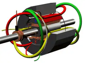
Photo: to illustrate the motor rotating.
Imagine your motor as a dance floor and Faraday’s Law as the DJ. The stator throws down a killer beat in the form of a rotating magnetic field—spinning invisibly like disco lights across the dance floor. This beat (or magnetic field) sweeps over the rotor, which is like a shy dancer waiting for the right moment to move.
Now, here’s where the magic happens. According to Faraday’s Law, anytime a magnetic field changes near a conductor (like the rotor), it’s like a friend grabbing you by the arm and saying, “Let’s dance!” This creates an electric current in the rotor. The rotor, no longer shy, starts grooving along with the magnetic beat. But here’s the catch—it’s always a half-step behind, like someone trying to follow an energetic partner who’s just a bit too quick. This slight lag is called “slip,” and it’s what keeps the induction going.
As the rotor feels the pull of the magnetic beat, it gets swept into the rhythm. The interaction between the rotor’s current and the stator’s magnetic field creates torque—the push or pull that makes the rotor spin. And spin it does, smoothly turning that invisible energy into powerful, mechanical motion.
Thanks to Faraday’s Law, the rotor keeps dancing to the stator’s beat, powering everything from conveyor belts to industrial fans. Without this invisible DJ making the connection, the motor wouldn’t turn at all. So next time you see a motor spinning, just think—it’s all about the magnetic groove making the rotor move!
Now, I suppose you are very clear about the working principle of the induction motors. I will organize the content into simple visual steps to make it clearer for you.
-

1.Creation of Magnetic Fields by Stator Windings:
A.The stator’s windings are energized by a 3-phase power supply. B.The three-phase supply generates magnetic fields that are offset by 120 degrees in time.
-

2.Induction of Current in the Rotor
A.The rotating magnetic field cuts through the rotor. B.Faraday’s Law of Electromagnetic Induction kicks in, inducing an electric current in the rotor conductors. C.Fun Fact: This induction happens without any physical connection between the stator and rotor!
-

3.Torque Generation and Rotation
A.The induced current in the rotor interacts with the stator’s magnetic field. B.This creates a force, or torque, causing the rotor to spin in the same direction as the magnetic field. C.Slip: The rotor always lags slightly behind the stator field’s speed. Without this “slip,” no induction would occur. Typical industrial motors have a slip range of 0.5–6%.
Here’s a simplified flow of the motor’s operation:

4. FAQs
1. Why is a 3-phase induction motor self-starting?
A 3-phase induction motor is self-starting because the three-phase power supply generates a rotating magnetic field in the stator. This field automatically induces a current in the rotor, creating the torque needed to start the motor without any external assistance. Unlike single-phase motors, there’s no need for additional starting mechanisms like capacitors.
2. Why do we use a starter in a 3-phase induction motor?
Starters are used to limit the inrush current when the motor starts. Without a starter, the initial current could be 5–7 times higher than the motor’s rated current, which might damage the windings or trip the circuit breakers. Starters, like Direct-On-Line (DOL) or Star-Delta types, reduce this current and ensure a smooth start.
3. What is the formula for RPM of a 3-phase motor?
The formula to calculate the RPM (revolutions per minute) of a 3-phase motor is:
RPM = (120 × Frequency) / Number of Poles
For example, with a frequency of 50 Hz and a 4-pole motor:
RPM = (120 × 50) / 4 = 1500 RPM.
This is the synchronous speed. The actual speed will be slightly lower due to slip.
We offer customized motor solutions to meet your specific application requirements
LUPMOTORS offers ac low voltage 3-phase asynchronous industrial motors of all types – Please contact us freely.
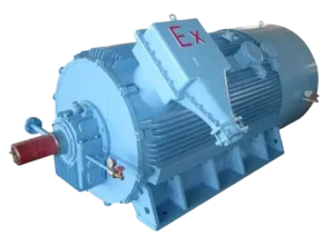
A Selection Guide for Explosion Proof Motors
Learn how to choose the right explosion-proof motor for hazardous locations. Understand classifications, T-Codes, and certifications to ensure safety and compliance!
Structure of Electric Motors | The Complete Guide
Discover the structure of electric motors, from stators and rotors to windings and bearings. Learn how materials impact efficiency, performance, and lifespan!
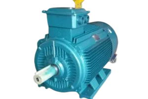
Motor Thermal Overload Protection | The Complete Guide
“Discover how motor thermal overload protection works, why it matters, and how to choose the right protector. Plus, take our quiz to test your knowledge!”
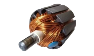
Brushed Motors vs. Brushless Motors: The Complete Guide
“Explore brushed vs. brushless motors: key differences, pros, cons, and which one fits your needs best!”
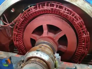
How to Test an Electric Motor: Tools, Methods & Procedures
Learn how to test electric motors with expert tools and methods. Discover step-by-step guides for insulation, resistance, and running current tests to ensure peak performance!
NEMA Motors vs IEC Motors: The Definitive Guide
“Explore the ultimate guide to NEMA vs. IEC motors. Learn key differences, efficiency standards, applications, and choose the right motor for industrial success.”


